The entire point of SMPS’s is that they are efficient. That, compounded with the fact that I started this experiment with the aim to better understand the design principles behind switchmode power supplies, meant that I couldn’t resist taking a few basic measurements to assign some numbers to the (very crappy) boost converter from chapter 2 .
I was going to build it out on a piece of perfboard first to reduce breadboard parasitics and to make sure that the intermittent connection issues I was having with my breadboard weren’t going to cause any issues down the line.
I built it out, but within 5 minutes the transistor died… I have no idea why, maybe it was killed by the large voltages caused by DCM ?
Anyway, I still took quite a few measurements when the circuit was on the breadboard, so lets dive in!
Math
Yes, there will only be math in this chapter.
Efficiency
The all important efficiency. Calculating efficiency at the most basic level really is quite easy, just divide the input power by the output power.
For example, one of my runs had a 330Ω resistor connected to the output. To calculate the efficiency under those circumstances, I measured input and output voltages and currents and did the following calculation.
$$ \begin{align*}V_{IN} &= 4.6V \\ I_{IN} &= 170mA \\V_{OUT} &= 13.84V \\ I_{OUT} &= 42mA \\ \\ \\ \eta &= \frac{P_{IN}}{P_{OUT}}\times 100\% \\ &=\frac{V_{OUT}\times I_{OUT}}{V_{IN}\times I_{IN}} \\ &= \frac{13.84\times 42}{4.6\times 170} \times 100\% \\ &\approx 73\% \end{align*}\\ $$
With the same 330Ω load resistor giving an output current of 41mA, I measured the efficiency at a few switching frequencies.
Efficiency vs Switching Frequency, Vin = 4.6V, Vout = 13.84V
| Switching Frequency (kHz) | Efficiency (%) |
|---|---|
| 5 | 61 |
| 9 | 73 |
| 11 | 73 |
I also did some measurements involving different load resistors, giving different load currents.
Efficiency vs Load Current, Vin = 5V, Vout = 13.84V
| Load Current (mA) | Efficiency (%) |
|---|---|
| 41 | 73 |
| 83 | 73 |
Nothing terribly exciting here.
From these preliminary results, I was actually not too disappointed, since an efficiency in the mid 70% is not too bad for a start in my opinion.
Now, I tried changing both the output rectifier diode between a silicon diode and a Schottky diode; and the switching transistor between a MOSFET and a bipolar transistor. The results speak for themselves!
Efficiency vs Output Rectifier and Switching Transistor, Vin = 5V, Vout = 13.84V
| Switching Transistor | Output Rectifier Diode | Efficiency (%) |
|---|---|---|
| TIP31C bipolar transistor | 1N4148 silicon diode | 65 |
| STP40NF03 MOSFET | 1N4148 silicon diode | 73 |
| TIP31C bipolar transistor | MBR340 Schottky diode | 75 |
| STP40nNF03 MOSFET | MBR340 Schottky diode | 81 |
Both the Schottky diode and the MOSFET made a huge difference when it came to efficiency. I guess its no surprise that all switchmode power supply implementations on the market use FETs, and most of them use Schotty diodes or even better, synchronous rectification.
Output ripple
Measuring output ripple is a pretty pointless exercise in this case IMO, since the breadboard, total absence of decoupling and long leads strewn everywhere are guaranteed to affect the measurement negatively (which is why I really wanted to build it out on perfboard first). Nevertheless, it’s still an interesting exercise.
Here is the output waveform, AC coupled, with an output current of 81mA:
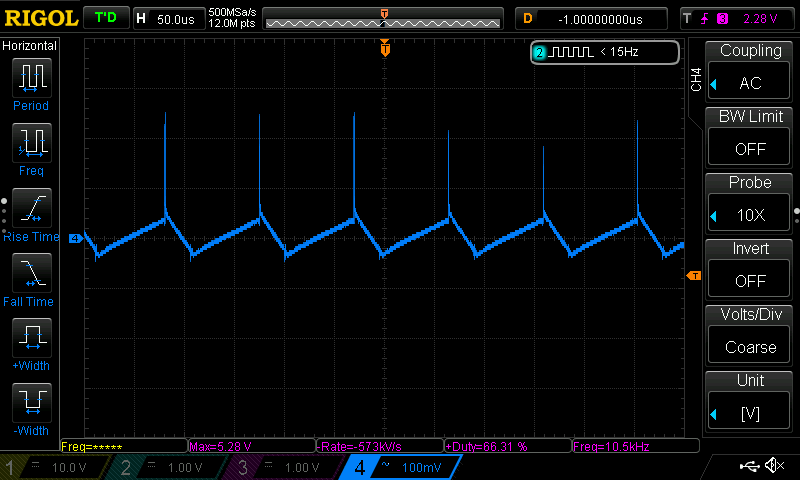
Yikes…
Those big spikes are probably due to the inductances of all the long breadboard jumpers and the lack of decoupling, so I will pretend that they aren’t there.
100mV peak to peak of output ripple for 13.84V output, which isn’t too bad until you consider that the load current is only 81mA…
Oh and did I mention that the coil whine was seriously annoying.
Load regulation
I was going to try to the load regulation of this boost converter. However I only managed to get 3 readings before it blew up, and all 3 of them were at really small currents.
And the worst (from a calculation standpoint) bit: the output voltage did not budge at all. So technically we have a load regulation of… 0%
Quiescent current
This one was measured on the perfboard version. Under no load, the circuit draws 6mA. That’s honestly neither here nor there IMO.
Final remarks
Like I mentioned, these measurements are made at pretty unrealistically small currents, and the construction of the circuit on the breadboard leaves a lot to be desired in terms of attention to low inductance paths, star grounding, decoupling etc. Hence, I don’t know how much value these results hold, apart from being an interesting exercise.
Gallery
There’s not much to see here, since its all math. However, I do think that this bodged on Schottky diode is pretty cute.
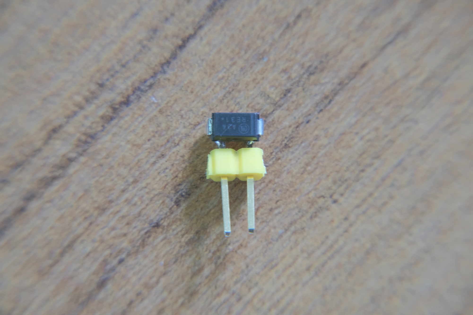
Upside down, so all the electrons are going to fall out.