Yes, this MIDI controller has a 4×4 grid that you have undoubtedly seen way too many times. No, it doesn’t have RGB
Will it actually get used? Probably not. But hey, its a great opportunity to learn some electronics! And implementing key matrices is not as trivial as you might think.
Schematic
First off, if you haven’t already, check out this excellent post by Dave Dribin to learn about ghosting and masking.

This is the classic way to wire up a key matrix of any number of rows and columns. The diodes are in there to prevent ghosting and masking. Dave’s page gives a really excellent explanation, but for the sake of completeness, I’ll give you the gist below.
Imagine for a second that the diodes weren’t there, and SW9, 14 and 15 were pressed at the same time. When we scan the second column by pulling PA5 high, we expect PB6 to be high and PB7 to be low. However, that won’t be the case!
Because there is nothing to block current flowing in the “reverse” direction, PB7 gets pulled high as well. Thus, the microcontroller thinks that SW10 is also pushed, when it isn’t: a ghost keypress.
Now, picture us pressing and releasing SW10. No matter what we do, the microcontroller sees SW10 as being pressed, thus SW10 is masked.
The code
There really isn’t much to scanning a key matrix, just pull one column high at a time, and see which rows are high/low. Right?
| |
Well, in theory, yes, that’s all you need to do, and on something slower like an Arduino Uno, it should work. However, the STM32 is much faster, too fast for its own good in this case.
In order to simplify the wiring inside the frankly already pretty cramped enclosure, I chose to use the internal pulldown resistors on PB3 to 7. According to the STM32F103’s datasheet, the maximum resistance in pulldown mode is 50kΩ, and typical pin capacitance is 5pF. So, we would expect a typical RC time constant of about 250ns.
Think about the behavior of the above code. First, all of the pins are set to LOW. If any of the switches in that particular column were pressed, the pin capacitance of the relevant rows starts getting discharged via the 50kΩ ish internal pull down resistors. We expect it to take around 250ns for the voltage at those pins to fall to 37% of their initial value, which in this case is about 1V.
At the same time, the code is energizing the next row, and then it immediately proceeds to sample PB3 thru PB7 to determine which buttons are currently depressed.
As shown above, this code is prone to a sort of spillover across columns, as the time between clearing PA4 thru PA7 and reading PB3 thru PB7 is around 250ns, which means that by the time the microcontroller goes to read those pins, those which are currently in the midst of discharging are barely on the edge of the logic low threshold of 35% Vcc. So, all sorts of undefined behavior happens.
So, you’d think that if we pull all the pins low at the end of the for loop, ie move line 4 to after line 6, then by the time the microcontroller goes to read the pins again they should have discharged well below logic low. Well, here’s where parameters which only have specified typical values and no min/max range can really screw you up. Take a look at the discharge curve of one of these pins.
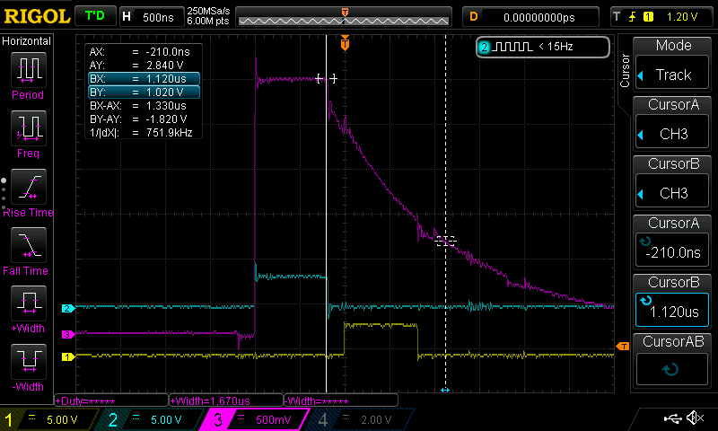
Channel 1 and 2 are hooked up to PA5 and PA4. Channel 3 is hooked up to PB6 while SW4 is depressed.
You can see that for my particular development board, the RC time constant is 1.12us. Assuming the internal pulldown is 50kΩ, that works out to a pin capacitance of 26pF. I don’t know if this is due to poor board layout, flux residue, or because I was really unlucky and my particular microcontroller just had a much higher capacitance for whatever reason. Or maybe I got fake STM32s (which is a real issue with these generic chinese STM32 boards by the way).
Anyway, if this happens to you, the code tweak would not have fixed it. And it would not be reliable at all anyways.
So, in the end, I still had no choice but to bodge on some external pulldowns to get the pins to discharge faster.
Just something to be aware about!