I really like rotary encoders as user input devices, they’re free of analog noise shenanigans, have no fixed positions, can be augmented with velocity control… Just a really nice way for the user to navigate around in menus or adjust parameters. That said, they do take up at least one extra pin per encoder compared to potentiometers, and of course, they require either polling or pin change interrupts to react to changes in the states of their pins.
Personally, I’ve never been a fan of the interrupt approach, its just really unreliable, and causes all sorts of timing issues with the code. In my opinion, rotary encoders should always be polled.
In trying to cram a bunch of stuff onto a small STM32F103C8 blue pill board, IO pins are really a scarce resource, 5 encoders taking up 10 pins just isn’t going to do it. Rummaging through my parts bin (every hobbyist seriously needs to have at least one parts bin), I found some CD4051 analog muxes that I have absolutely no idea when and why I purchased. Perfect!
Hooking everything up

I’m still a newbie when it comes to KiCad, why do these CAD packages have to be so different from one another……
Using a pair of these analog muxes, you can connect up to 8 rotary encoders using just 5 pins.
Ordinarily, rotary encoder circuits on the internet will include some sort of RC network to debounce the outputs. That’s actually a really good idea to ensure truly reliable operation, but I chose to omit them here, solely because I really, really didn’t want to have to painstakingly solder on 0805 ceramic caps to perfboards (didn’t have room for through hole caps), and also because the way the encoder inputs are interpreted is inherently quite immune to undefined state transitions, as will happen with contact bounce, more on that later).
I initially wanted to use PC15 to interface with control pin C of the mux, as that would allow for more elegant code later on. However, my blue pill has a 32.768kHz oscillator populated, which causes PC15 to be tied to ground. Talk about times when cheap boards from China come with “extra” components that not only you don’t need, but actually come-a-gutsa because of them…
Interpreting the encoder states; and how to get away without debouncing
So, we’ve established that we will be polling the encoder at fixed time intervals. In order to deduce whether the encoder has been rotated or not, and if it has been, in which direction, we will compare the current state of the encoder pins to their states the last time we sampled the input pins. This series of graphics from Wikipedia sums up the approach nicely.
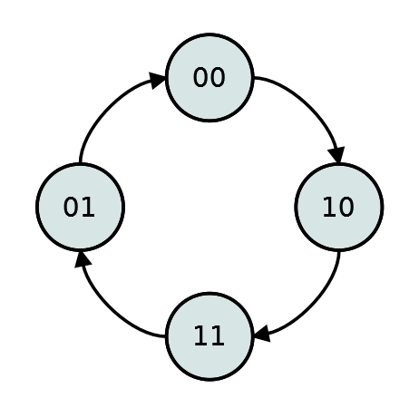
Clockwise rotation
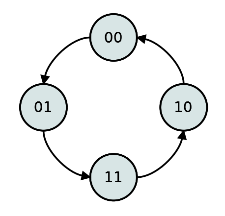
Anticlockwise rotation
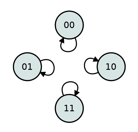
No rotation
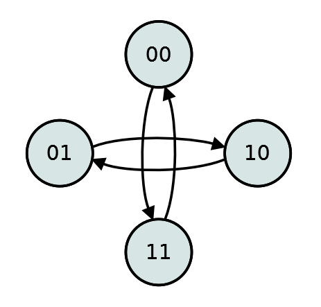
Invalid state changes
By Lambtron - Own work CC BY-SA 4.0 , Link
By using this method, we can get away with not debouncing the rotary encoder inputs at all! This is because should contact bounce occur, by nature of the construction of rotary encoders, only one of the two pins is undergoing a state change at any given time, ie bounce only occurs on one pin at a time.
Hence, any contact bounce will result in one of the invalid state changes (because the only way to get one of the valid state changes is, well, if there were a valid state change), thus we can just ignore it.
Code breakdown
I chose to use timer 3 to periodically poll each one of the encoders. Since polling encoders isn’t as sensitive to inaccurate timings as, say, dimming LEDs with bit angle modulation , I made sure to set the priority of the encoder timer ISR to something higher (lower priorities are prioritized by the STM32). Check out part 4 for a primer on how to set up timer interrupts. The priority settings can be changed under “preemption priority” in the NVIC tab of the device configuration tool.
First, some global variables to keep track of everything:
| |
Then, in the timer 3 ISR:
| |
This LUT (lookup table) based approach is a really nice and efficient way of implementing rotary encoders, as it saves the need for a whole bunch of if else statements like in some Arduino code examples out there. An example is the easiest way to understand how it works.
Lets say the encoder has been rotated clockwise by 1 position, currentReadoff takes the current state of pins A and B and joins them together into a 2 bit value representing AB. Lets say that between updates, the value went from 10 to 11.
The code then takes the 10 and 11, and joins them into the value 1011. 1011 is 11 in decimal. Therefore, element 11 in our LUT should be set to 1. encoderValues[i] is then incremented or decremented accordingly. For all forbidden state transitions, we just need to set those values in the LUT to 0, meaning that encoderValues[i] will remain unchanged.
This code assumes that the encoder only turns 1 position between updates, anything else and the state transition you get may very well be one of the invalid ones. So, care must be taken to ensure that the ISR fires frequently enough to capture the fastest rotations you expect. Also bear in mind that with the code above, only 1 of the 5 encoders is updated each time the ISR fires, therefore the actual polling rate of the encoders is one fifth of the frequency at which the ISR fires. In my case, I have the ISR firing at approximately 4kHz, and have not encountered any perceivable skipping issues.
After the updating of encoderValues[i], the code sets the mux to connect the next encoder in line to PA9 and PA10. According to the datasheet, with 5V logic the CD4051 needs about 700ns max to react to a change in the selected channel, and that time is longer for 3.3V logic. That’s probably nothing to worry about, but just to be safe, its better to change the channel of the mux at the end of the ISR, so that we can be sure that whatever is on PA9 and PA10 the next time around is free from glitches.
I’d like to bring your attention to lines 15-18. Initially, PA15 was supposed to be PC15. That way, I could just set bits 13-15 of GPIOC->BSRR to currentEncoder to make everything just that much more efficient, but alas, sometimes that just isn’t possible.
Some of my mistakes
Being a noob, I must admit that it took many tries to get to the above code. I’d like to share some of my mistakes with you, as sometimes the reasons they cause issues down the line isn’t obvious at all when you first write the code, and that ends up causing a lot of facepalming.
Initially, I thought I was being cool using fixed width unsigned ints for everything. That was fine for stuff like data to be sent over I2C, since we are dealing with 8 bits every transfer anyway. But, for counters that will be incremented and decremented like this, that is a supremely bad idea as overflow and underflow can really break everything.
In the main loop, I’m handling encoder rotation like this:
| |
increment is then used to update MIDI CC values, and to navigate up or down the menu.
Seems fine, no? I quickly ran into a bunch of issues where the encoder will randomly work sometimes, and just stop updating occasionally. Even more strangely, this issue seems to get better the more I fiddle around with the encoders.
Turns out, it was due to me writing this bit of code in the ISR:
| |
Since I was using unsigned ints, ostensibly to conserve RAM (as if I didn’t have a huge excess of it in the end), I thought I was being clever by manually constraining the values to prevent overflow. Not only is the above implementation NOT how a constrain function should be implemented, in the beginning, when encoderValues is at its initialization value of 0, well, any counterclockwise rotation will simply be constrained off! So turning the knobs counterclockwise does absolutely nothing, which left me puzzling over why the menu wasn’t scrolling.
Then if you rotate it clockwise a little, you gain a little in encoderValues, this now gives some wiggle room to rotate back counterclockwise, and everything seems to work. But, the counterclockwise rotation stops doing anything as soon as you rotate counterclockwise by the same amount as you rotated clockwise.
This is the reason why the problem seemed to get better the more I fiddled with the knobs. It was simply encoderValues increasing to give me more room to play with.
The lesson: don’t try to be smart and use unsigned ints unless there is a very, very good reason for it. Fixed width ints and unsigned ints are probably not warranted for unless you are absolutely struggling for RAM.
Then, there was the issue of 2 of the encoders affecting each other’s values. Turns out that a solder dag got in between pins C an B on one of the muxes causing everything to just break… I thought I had some sort of silly software bug again, until I busted out the scope and gave everything a through probing. And the worst part is, it was one of those solder dags held on by flux residue, causing the issue to only crop up intermittently.
Lesson? Perfboard is great, fun and convenient, until it isn’t.