While PWM certainly is a mighty fine option to add dimming control to LEDs in your projects, there may be certain cases where it simply isn’t the best option. Maybe you don’t have enough PWM capable IO pins on your microcontroller? Or maybe manually bit-banging PWM control takes up too much CPU time? And you certainly aren’t about to fork out a bunch of cash for something like a TLC5940, and cheaper chips either are out of stock, are only stocked in pain-in-the-neck QFN packages, or are hopelessly backordered.
Bit Angle Modulation, aka BAM: A better-than-nothing solution
Before we go on, it is important to make it clear that, like software PWM, BAM requires periodic execution of code, which may or may not add a lot of complexity to your project. That being said, BAM is a lot more efficient than PWM in terms of CPU time usage (more so as the resolution or number of bits increases), and so, can be a great choice.
The main idea behind PWM and BAM is to rapidly switch the LED on and off, achieving grayscale control by varying the ratio of time the LED spends being turned on and off.
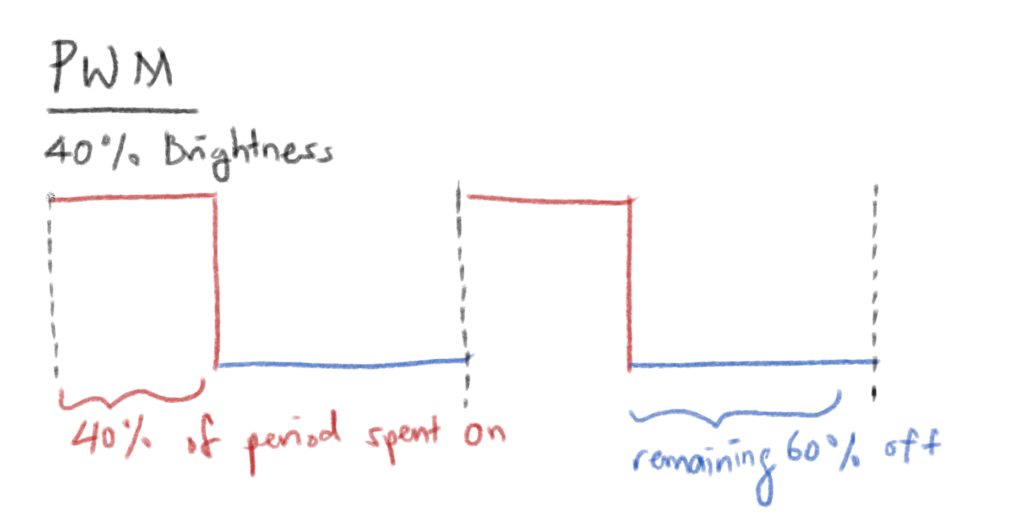
PWM does this in a really straightforward way: want 40% brightness? Just turn the LED on for 40% of the time, and off for 60% of the time.
BAM essentially also does the same, although in a slightly more involved way. Instead of just having one continuous on period followed by a continuous off period, it splits the entire period up into as many pieces as there are number of bits of grayscale resolution, each slice twice as long as the previous slice, and selectively turns on the LED in a particular combination of these time slices to achieve dimming.
So lets say we have 8 bits of grayscale resolution. $40% \times 255 = 102$. And 102 is 01100110 in binary. Therefore, to achieve 40% of the period being on, we read the binary number from right to left, and turn on the LED if the corresponding bit is a 1.
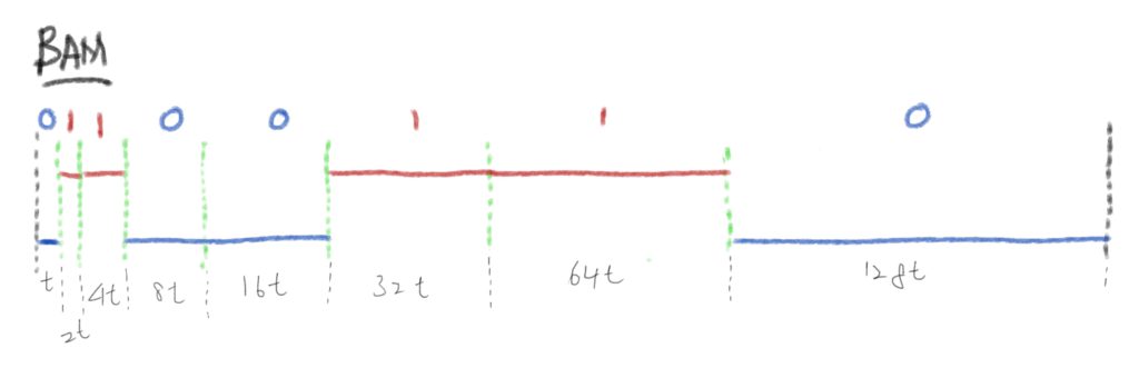
The widths are not to scale.
You might ask: why bother? Isn’t PWM more intuitive and therefore easier to implement.
Well, yes, yes it is. However, it has one major flaw as mentioned above, it requires way, way more CPU cycles than BAM, and this problem gets worse as the grayscale resolution goes up.
Think of it this way: in the BAM example shown above, for one period, the CPU only needs to check whether or not to toggle the LED at the very beginning of the cycle and at all the green divisions, which adds up to 8 times per cycle for 8 bit resolution. PWM however, will have to do the same thing 256 times, which can really hog up the CPU, especially if all the LED checking and toggling happens in timer interrupts (it probably will for the vast majority of implementations).
Setting up the timer interrupt
Like PWM, BAM also requires its code to be run at fixed (or increasing, depending on how you look at it) time intervals.
The most natural way to achieve this, IMO, is with a timer interrupt.
I chose to use Timer 2 to control everything. So, if you’re following along, go ahead and enable Timer 2 and its corresponding interrupt.
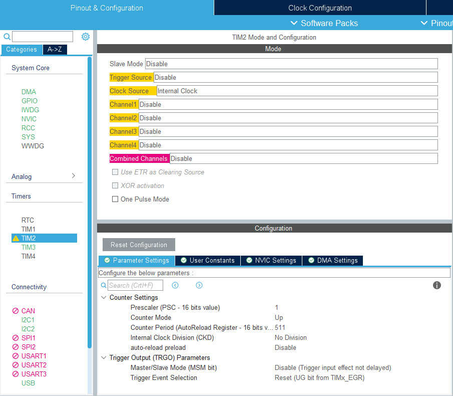
I played around with the counter period settings until I got a satisfactory refresh rate that didn’t hog up the CPU too much (because while you can absolutely go ham and have super duper fast updating LEDs, the amount of code run each time the ISR is called is fixed, so the more frequently the ISR gets called, the more CPU time you are going to use up.
I should also point out that I have the clock configured to pump in 72MHz into Timer 2.
We are going to be using the on-the-fly prescaler feature of the STM32F103’s timers to double the prescaler every time the ISR is called, and resetting it back to 1 every 8th time. The prescaler essentially divides the incoming clock, so doubling it every time means the time interval between ISR firings is doubled progressively throughout the cycle.
Then, its just a matter of toggling the LED (or LEDs) if necessary.
The code
| |
brightness[i] contains the brightness value of the LEDs from 0-255 (for 8 bit grayscale control).
BAMIndex keeps track of which division we are currently at; basically it is there so we can know when to reset the prescaler.
You can add/remove/modify lines 5-6 however fits your use case.
Then, crucially, we need to actually enable the update interrupt, and of course, start the timer so that it actually does anything. Note that the device configuration utility in STM32Cube IDE does not do this for you, so if you are playing around with hardware timers on these microcontrollers, that’s something to watch out for.
In static void MX_TIM2_Init(void), add after /* USER CODE BEGIN TIM2_Init 2 */
| |
Then, when you are ready to allow the LEDs to start, use:
| |
And there you go, you should now have grayscale control over as many LEDs as you desire!