Staying on the topic of ways to use the I2C peripheral of the STM32F103 microcontroller, today, I’m going to discuss how I implemented a basic bi-color LED matrix based on the MCP23017 I2C I/O expander. This is not a full blown, colorful RGB LED matrix – its literally “monochrome”, but with the massive RAM of these STM32 microcontrollers, a full color LED matrix certainly seems doable with some tweaking, although at that point, I don’t see why wouldn’t you go for WS2812 or its alternatives instead.
The premise of all of this
Multiplexing is one of those things that feels simple enough to implement, yet has so many traps for young players that can really complicate things.
There are many ways one could implement a basic LED matrix, the most simple is undoubtedly to just refresh it once every time the main loop executes. However, if your program has lots of sensor polling, interrupts, sending and receiving data; basically anything that causes the loop execution time to fluctuate, the changing timing between refreshes is going to manifest as flickering, not great.
A better way to do it is to update the LED matrix with a timer interrupt, which can work really well. However, this project already has many interrupts going all over the place, so I really wanted to avoid adding more. Plus there is a much more elegant way to achieve this
Enter the DMA peripheral
The DMA peripheral allows us to continuously ferry data from one place in memory to another, all without hogging precious CPU cycles or introducing concurrency related issues. This is brilliant, because it allows for an implementation that is almost ASIC-like. To update the LED matrix, all you need to do is to update a certain block of memory in a certain way (which we will get to shortly), and the DMA takes care of the rest. It really is like programming with a dedicated LED matrix peripheral, and its plenty scalable too, although I suspect if you’re implementing an LED matrix that has more LEDs, shift registers would make more sense.
Code breakdown
Before continuing on, make sure you are familiar with how the I2C peripheral works on the STM32F103 series of microcontrollers. You can check out parts 1A and 1B for more details.
I2C and DMA peripheral setup
First off, using the device configuration tool in the STM32Cube IDE, we are going to enable the DMA peripheral, in particular, the DMA channel associated with I2C 1.
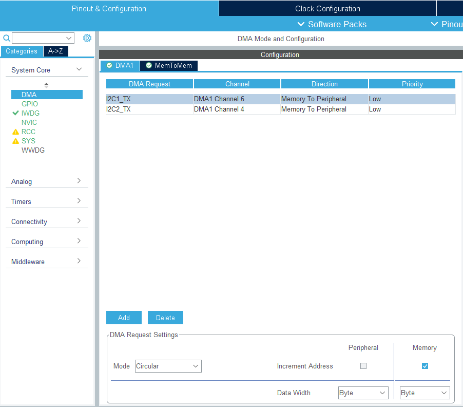
A brief explanation of why I chose these settings:
Firstly, the DMA on the STM32F103 has 2 modes, normal and circular. In normal mode, the DMA sends the number of bytes/words that we specify, then once it’s done, it just sits there and does nothing else. In circular mode however, it resets its base pointer and byte counter, essentially reloading itself with the settings that we specified at the very beginning. Since for this application, we want the DMA to keep on sending data from the a certain buffer in RAM, circular mode is what we want.
The DMA has 2 internal pointers, one points to the location in memory where the data is read from, named the memory address; and another which points to the destination where the data is written to, which is known as the peripheral address. In this case, we want to read data from a buffer, which contains the states of the output pins of the MCP23017 (with control bytes sandwiched in between) for each of the 4 rows of the LED matrix, ie, the memory address should be incremented so that the DMA cycles through each row of the LED matrix, which achieves the whole multiplexing thing. All this data is to be sent out via I2C to the MCP23017, hence we want to transfer everything to I2C1->DR. Hence, the peripheral address should be set to stay put at I2C1->DR‘s address.
The data width setting basically tells the DMA how many bytes to send per transfer, and thus how many positions to increment its pointers (if specified). I2C sends out one byte at a time, so we’ll leave both at “byte”.
| |
This setup is very similar to what I’ve covered in Part 1B , so I will spare you the details. Note that in this case, the MCP23017’s alternating behavior between port A and port B actually comes in handy, since it allows for a very elegant way of updating both the column and rows without having to send any control bytes in between, greatly streamlining the implementation.
LEDMatrix[4] stores the current state of the LED Matrix, one byte per row. The lower 4 bits are the states of the green LEDs, and the upper 4 bits are for the red LEDs (or whatever color LED you’re using).
LEDMatrixBuffer[16] stores the data that we are going to send to the MCP23017 via the DMA. In this implementation, each row update requires 4 bytes, hence the 16 byte long buffer.
Filling up the DMA buffer

If you take a look at the schematic, the bytes to be sent over to the MCP23017 to update the LED matrix are really quite straightforward to derive. Basically, to update a column of LEDs, we just need to ground the corresponding cathode of that column of LEDs, while pulling those of the other columns high. Then, its just a matter of setting the corresponding pins in port B to high or low depending on whether or not the LED is on.
However, there is one detail that you need to be wary of when implementing stuff like this. Due to speed at which the MCP23017 updates its output ports, there is a period of time when the pins on port A have progressed to the next column, but the MCP is still receiving the data for port B, port B still retains the state of the previous column, this causes the state of the previous column to “bleed” over into the current column. To fix it, we simply need to clear the LED matrix entirely between subsequent column updates. 2 bytes to clear both port A and B, 2 bytes to write their new states, 4 bytes in total per column.
With that in mind, a little routine like this can be used to fill in each of the 16 bytes in LEDMatrixBuffer[16] to update the LED matrix.
| |
DMA setup
The final piece of the puzzle is to get the DMA to continuously write the data out to the MCP23017.
| |
Lines 3-7 contain the setup stuff for the DMA. For whatever reason, the code generation for the DMA initialization doesn’t seem to be doing the business, hence we need to manually configure all the relevant registers. It’s not too difficult to wrap your head around what all the bits and registers do tho, the DMA of the STM32F103 just isn’t that complicated of a peripheral, and the reference manual does an adequate job of describing everything.
Then, it’s just a matter of configuring the I2C 1 to send a DMA request every time its done sending out a byte. The DMA should now continuously feed the data register with stuff from LEDMatrixBuffer[16].
If you check the reference manual, as with all setup stuff, ST recommends that you actually set everything up completely before starting I2C transactions. However, there is one pesky byte we need to send over first, which sets the pointer in the MCP23017 to GPIOA. Turns out, we can actually send that byte over first, then immediately enable DMA requests, and it ends up working just fine.
And that’s it! The DMA should now handle the all the multiplexing of the LED matrix automatically, saving us a whole bunch of timing headaches. All that has to be done if we want to change what’s displayed on the LED matrix is update LEDMatrix[4], then run the for loop that fills in LEDMatrixBuffer[16] once. Convenient indeed!