The problem with the simple approach
In part 1A, I presented a simple approach that did the job quite well. However, since the program has to wait for the slow I2C bus to send more than 30 bytes of data every single time the LCD is fully updated, it simply wouldn’t cut it for a MIDI controller which not only has to send keypresses with as low a latency as possible, but also has to do a whole bunch of timing critical stuff like bit angle modulation, polling five rotary encoders, and multiplexing an LED matrix. Something more efficient was needed.
Enter I2C Event Interrupts
Ultimately, after considering stuff like DMA, I decided that using I2C event interrupts is the way to go. The idea was to trigger an interrupt every time the I2C bus finishes sending a byte. The interrupt then decides to set or clear the RS pin, as well as whether or not it should pulse the EN pin. It also loads the next byte to be sent into I2C2->DR. Its really quite a nice solution IMO, since I just need to call a function to kick off an LCD refresh, and the interrupt takes care of the rest without tying up the CPU.
The STM32F103’s I2C peripheral essentially has 2 interrupts, the event interrupt and the error interrupt.
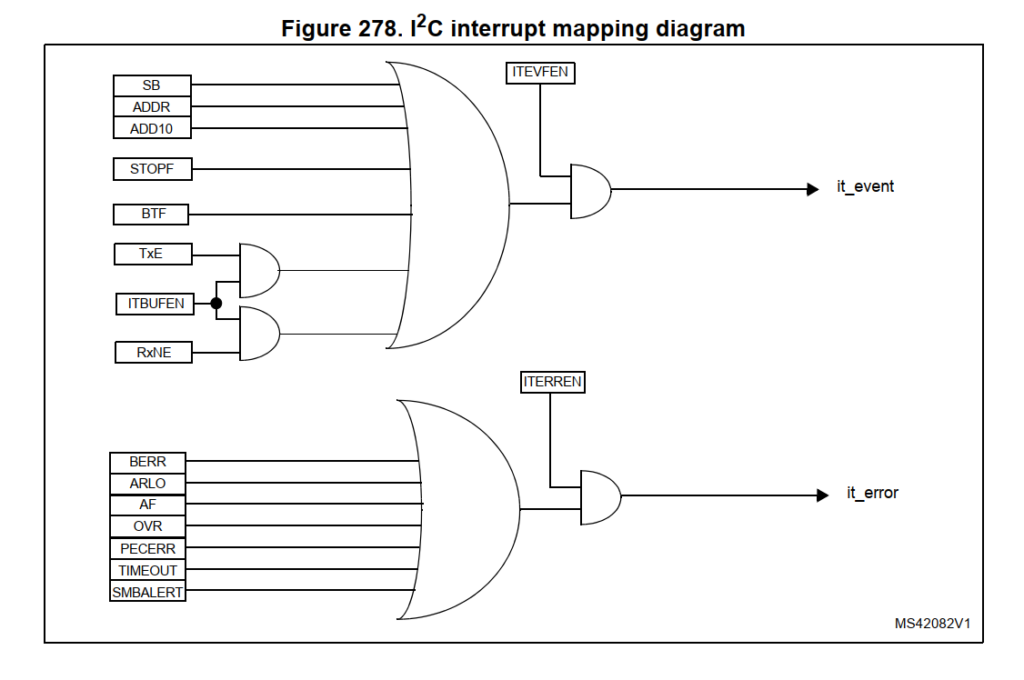
From the Reference Manual RM0008
Recall from Part 1A
that every time a data byte is sent out from the peripheral, the BTF bit is set. Notice that BTF is tied to the upper OR gate, which triggers it_event AKA the I2C Event Interrupt, so, that’s where we will begin.
Setting up interrupts in STM32Cube IDE
Using the device configuration tool/starter code generator thingy, we can make things a little easier for ourselves.
First, go ahead and enable the I2C Event Interrupt code generation here:
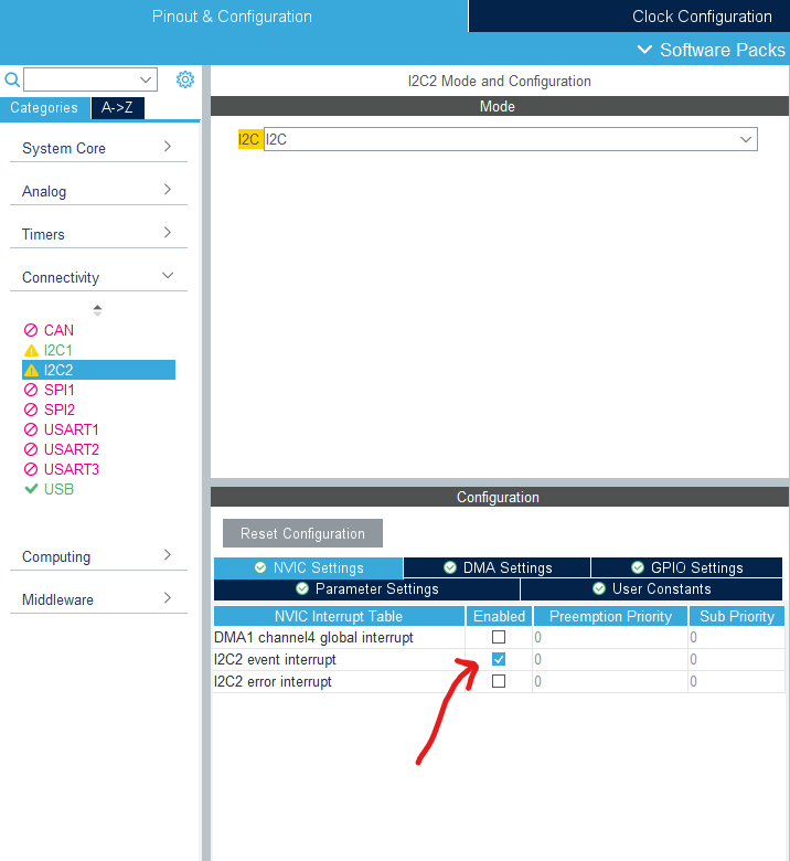
Then, remember to get the tool to also initialize the NVIC correctly for us, otherwise absolutely nothing will happen and you’ll be left wasting yet another huge chunk of your time.
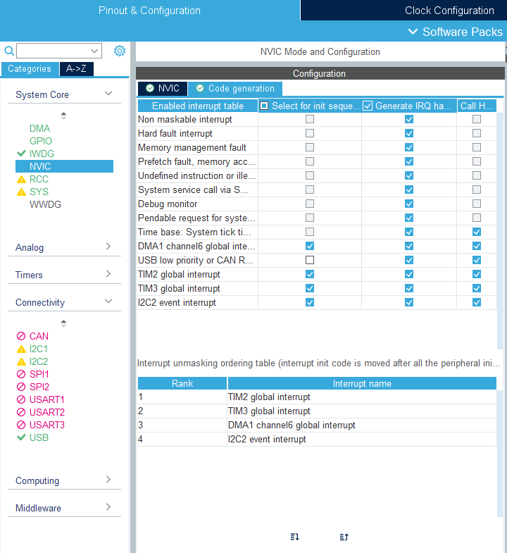
Check I2C event interrupt in the select for init sequence column
This adds the following lines in the MX_NVIC_Init() function.
| |
Now go ahead and open up your stm32f1xx_it.c file. It should contain a I2C2_EV_IRQHandler(void) function, which is where all the code we want to run in the interrupt is located.
Warning: when using the STM32Cube IDE, do respect the /*USER CODE BEGIN*/ and /*USER CODE END*/ comments. The starter code generator looks for these lines, and preserves the stuff in it if you change something in the device configuration utility and generate new starter code. If you write anything outside these lines they will get deleted.
Before continuing, I strongly recommend that you connect the RESET line of the MCP23017 to the RESET line of the microcontroller. That way, every time you make incremental changes to the code and flash it, which involves resetting the microcontroller, you guarantee that the MCP23017 is in a well defined state. This ensures that all the initialization code can run as expected, as we will soon be making changes that would change the addresses of the registers.
Code breakdown
The setup
First, a setup function. Since we want to use an interrupt to feed the character data to the LCD, we basically only want to continuously write to the output register of the MCP23017. Hence, we need to disable the auto-incrementing of the internal address pointer, which is enabled by default, so that we won’t have to stop, start again and write the address pointer every single time we want to update the output bank. This is achieved by setting SEQOP to 0 in the IOCON register. The chip now enters what Microchip calls Byte Mode.
Recall that on reset, the MCP23017 automatically goes into the mode where the registers for bank A and bank B are interleaved; this is the behaviour when the BANK bit in the IOCON register is 0. In the datasheet, there is a sneaky line that goes:
A special mode (Byte mode with IOCON.BANK = 0) causes the address pointer to toggle between associated A/B register pairs. For example, if the BANK bit is cleared and the Address Pointer is initially set to address 12h (GPIOA) or 13h (GPIOB), the pointer will toggle between GPIOA and GPIOB. Note that the Address Pointer can initially point to either address in the register pair.
Section 3.2.1 in the MCP23017 Datasheet
Well, that’s not what we want is it… It looks like we have no choice but to set BANK to 1, which completely changes all the register mappings and would thus require us to change all the initialization code… Unless we reset the MCP23017 every single time we reset the microcontroller. So all in all, this is what the setup function would look like:
| |
A few things before we go on, LCD_Address is the I2C address of the MCP23017 shifted left by 1 bit. Lines 3-5 and 20-22 avoid interrupt related lockups I was talking about in Part 1A . TIM2 handles the LED dimming, while TIM3 handles encoder polling. Essentially, I had to pause these interrupts because merely disabling interrupt requests messes up the timing of the bit angle modulation, causing the LEDs to flicker. An in depth breakdown of that in a later part.
I should also note that I set the I2C2 Peripheral to 100kHz; no point going faster if the LCD itself needs more time to process characters. You might be able to go up to 400kHz, but I did run into issues. YMMV.
LCD print functions
These functions start the process of printing a either the top line or the bottom line of the LCD. I chose to do it this way because you can’t just print a CR LF and expect the cursor to move to the second line; line changes are commands, which requires the whole shebang of setting and clearing RS, calculating offsets and control bytes etc. So, it was just easier to split it to 2 different functions, each preprogrammed with the requisite stuff.
| |
All the variables here are global variables. Yes, I know that global variables can cause issues especially when concurrency is involved, but its just simplifies the code so much, and if you’re careful and really think/test it through you should be fine. This is not some mission critical stuff where lives are at stake.
For those of you who are unfamiliar with the C printf family of functions, the line snprintf(LCDBuffer, 17, "%-16s", str); basically takes whatever string str is, extends it out to 16 characters so it fills an entire line in our LCD, and stores the first 17 bytes of it into the char array LCDBuffer.
Why 17 and not 16? C strings are null terminated, so we need to account for a 16 byte long string, plus 1 null byte.
Line 8 pulls the RS line low, this tells the LCD that the next incoming byte is a control byte, which will be the command to set the cursor position.
currentLCDByte is used in the interrupt service routine to keep track of the number of bytes sent over the I2C bus in this current round of printing. We reset it to 0 every time we kick off a new transfer.
isLCDPrinting is a flag which is checked in the main loop of the program to make sure that the LCD isn’t currently being written to before it requests another update of the LCD. Since we’re about to start printing to the LCD, we set the flag.
cycleEN is a flag checked in the ISR to let it know whether or not it should pulse the EN pin every time it fires. This is important because I2C 2 is not just used for the LCD, and thus, we wouldn’t want the E pin to be pulsed causing the LCD to shift in random data every time a BTF is raised by I2C 2.
Now, you may have noticed that I am enabling the I2C event interrupt after loading in the control byte to the Data Register. This is so that the ISR does not get fired during the part where we specify the register address of the MCP23017. The first time the ISR will go off is when we are setting the cursor position of the LCD.
The heart of it all: the ISR
Here is where the magic happens. The ISR handles stuff like setting the RS pin, pulsing the E pin, and letting us know when the LCD is done updating, and saving parameters to EEPROM (more on that in Part 2 ). It is really, really twisted, but I’ll try my best to explain what’s going on. For now, all the EEPROM stuff will just get a passing mention; our main focus is the LCD stuff.
It is really, really long for an ISR, but hey, so far I haven’t encountered any issues yet, so I’ll roll with it.
| |
The way this ISR code works is, once an LCD update is called for, it feeds the I2C peripheral with 16 bytes of data (1 line on our 16×2 character LCD). Every time a byte has been sent over, it pulses the EN pin to get the LCD to shift in the data. Then, it checks if there is stuff queued to write to the EEPROM, if there is, it writes it, otherwise, it just sends an I2C stop condition.
Broadly speaking, you can think of this as having 2 mutually exclusive main running states, it is either in the middle of printing to the LCD, or saving stuff to the EEPROM.
At the very beginning, we check to see what actually triggered the ISR, and only execute the body of code if its the BTF flag.
Then, we check if the current state of the ISR is saving stuff to the EEPROM. If it isn’t, we proceed to the LCD stuff.
The next section checks if the EN pin should be cycled. Note that I had to fiddle around with the timings since the MCP23017 does require some time for its outputs to take the values we send to it over I2C.
Imagine that we just called the one of the LCDPrintString() functions, and the ISR is firing for the first time. Now, the RS pin is low, cycleEN is set and the cursor position control byte is present on the outputs of the MCP23017. The ISR pulses EN to shift in the control byte, then pulls up the RS pin to prepare to print characters to the LCD. It also increments currentLCDByte, and loads in the first byte in LCDBuffer into the I2C Data Register.
For the subsequent firings, the ISR basically pulses the EN pin, increments currentLCDByte and loads the next byte in LCDBuffer into the I2C Data Register.
When currentLCDByte reads 17 (1 control byte+16 character bytes), we are done printing this current line of the LCD. So, we can clear cycleEN so anything that triggers this ISR won’t shift garbage into the LCD, and send the stop condition to cap it off. Then the code checks if there is stuff pending to be saved to the EEPROM, if there is, it initiates a sequence of transfers to do just that. Otherwise, isLCDPrinting is cleared, telling the main loop that it can request another LCD update.
Usage in main loop
| |
After all this hard work, we are rewarded with a very simple way of efficiently updating the LCD, very useful for, say, displaying the current value of a MIDI CC channel.
There are a few global variables and buffers which are used to keep track of everything, once again split into the top row and bottom row for simplicity. Then at the end of each loop execution, if the LCD is free and an update is queued, the corresponding LCDPrintString()function is called.
Conclusion
This was a lot of hard work, as it was the first time I’ve done a project on the STM32F103 platform (not including those done through the Arduino IDE, that is). It took a lot of fiddling to get to this point, and the code is far from perfect. Nevertheless, I hope you’ve learned something from my experiences, and now feel just a little more confident using the STM32Cube IDE and the really nice STM32 microcontrollers.
If you use this approach, you should be rewarded with a seriously responsive and fluid LCD interface, which is fully non blocking, and most importantly easy to use and scale throughout the code. Of course, how smooth the overall user experience is still depends heavily on the other parts of your program, but you can rest assured that the LCD code isn’t the thing holding you back.
Happy making!