This was one hands down the most challenging and frustrating part of the entire project, involving hours of staring at the reference manual for the STM32F103 microcontroller series trying to figure out why the I2C peripheral kept locking up. Maybe its just me, but the diagrams and explanations in the reference manual for the I2C peripheral were not exactly intuitive, especially since they throw in a whole bunch of concurrent events that occur throughout the process of sending/receiving data packets, and the registers you have to read/write to placate the peripheral changes in a kinda confusing way depending on the number of data packets, the speed at which the slaves respond, etc, etc, etc….
So, I think a good place to start is to walk through the STM32F103’s I2C peripheral, and what you need to know to implement basic I2C read and write functionality. That way, hopefully you’ll be able to easily use the I2C on these nice little microcontrollers without having to pull all your hair out.
I2C on the STM32F103 series – the basics
First, enable the I2C peripheral in the STM32Cube’s starter code generator utility. There, if you so desire, you can increase the I2C speed to something faster, which is really helpful to reduce wasted CPU cycles when your I2C code is blocking. You should now be set to follow along.
Write operations
To give you some idea of what is required to do a basic write operation based on the ST’s Reference Manual RM0008, here is their transfer sequence for I2C master transmitter mode:
Yeah… Huge difference from something like an Arduino in terms of beginner-friendliness. Even stepping through the sequence, it is pretty hard to follow along and intuitively visualise what is going on under the hood.
So, lets take it step by step from here. The absolute bare minimum code required to use I2C to transmit data looks something like this:
| |
Note that I2C2->DR essentially means we are writing to/reading from the Data Register of the I2C 2 peripheral (look up “arrow operator in C” if you don’t know what it’s all about).
| |
First we start it off with sending a start condition, by setting the relevant bit in the I2C Control Register 1.
Then, according to the diagram, we need to wait for the peripheral to be done with sending the start bit, which is EV5. The peripheral sets bit 0, called the Start bit (SB) of its Status Register 1 when its done doing all the start condition stuff, so I chose to use the most naive way to monitor that bit: polling it. Also, by polling it, we are essentially continuously reading the Status Register 1, which together with the next line, will have the effect of clearing this bit in preparation for the next transfer.
| |
We now write the address of whatever device we want to talk to in the Data Register. The catch here is unlike the Wire library in the Arduino ecosystem, we have to manually specify whether the upcoming transfers will be reads or writes, by setting or clearing the last bit of the first byte to be sent. In other words, the first byte to be sent off by the I2C peripheral is the address of the I2C device, with an additional bit tacked on to it. The I2C peripheral itself also takes note of this last bit, and sets its state to transmit data or receive data accordingly.
Once the I2C peripheral is done transmitting the address and receives an acknowledgement from the target device, it then sets the ADDR bit in Status Register 1, which is EV6. Then, annoyingly, to clear the ADDR bit, we also need to read Status Register 2. Here, I chose to read Status Register 2 and check if the second bit (TRA: 1 if the I2C peripheral is transmitting data, 0 if it is reading data) is 0, as in a write operation like this it has a well defined state and will not cause any unforeseen problems. Then, finally, we need to wait for the TxE bit to be set (EV8_1), signaling that the Data Register is now empty and is ready to accept new stuff.
| |
We then load our data (8 bits) into the Data Register. Here is a bit that I found to be confusing: in the transfer sequence, Data 1 and EV8 (which is TxE = 1) are shown to be concurrent…what? How can the Data Register be loaded and empty at the same time? Turns out that the Data Register is like a 1 position queue, ie, when you load stuff into the Data Register, assuming all the requisite initialization stuff has been taken care of, it is immediately flushed into the output shift register (hidden from us) to be transmitted. Once this happens, the Data Register is now empty, hence EV8 and TxE = 1, and you are free to load in the next data to be queued for transfer as soon as the current one is done.
So basically, you just repeat these 2 lines for however many bytes you want to send out, but, look out for the procedure for the last byte, since it has extra stuff we need to take care of. Well, not quite, although the transfer sequence diagram sure makes it seem so!
| |
Now, we arrive at the last byte to be sent out. As usual, we wait till the data has been shifted into the output shift register, then according to the transfer sequence, we need to wait till BTF is 1 (EV8_2), before setting the STOP bit in Control Register 1 to signal the I2C peripheral to generate the stop condition.
While that certainly is the recommended way to do it, and probably how you should be doing it too, I have found it to be completely unnecessary, since setting the STOP bit is like queueing the stop condition – when the peripheral is done with whatever it is doing, it will service this request of ours and send the stop condition.
At this point, I should point out that BTF is kinda like TxE. TxE signals that the Data Register is empty, ie the data has been transferred to the output shift register (which is not accessible by us). BTF, on the other hand, signals that the output shift register is empty, ie data has been transferred out to the device, and there is nothing queued up in the Data Register to be transmitted, hence why we check for it to be set for the last bit to be transferred.
Read operations
In my opinion, read operations are much more confusing than write operations, since the requirement to check bits and clear registers is somewhat stricter than for write operations.
If you thought the transmit transfer sequence was bad, this one is a lot worse….
The code:
| |
Right off the bat, we have:
| |
A quick in primer: for I2C, a rule of thumb is the device which is receiving the data has to send ACK pulses after it receives each byte, to let the sender know that all is good (regardless of whether the device is the master or the slave). Then, if the receiver is the one controlling the number of bytes to be transferred, it must send a NACK (No Acknowledge) condition after the last byte has to be received has been received, more on that later.
So, since we want to receive data, we need to enable ACK, by setting the ACK bit in the Control Register 1.
| |
Now, then, we can proceed to send a start condition to kick off the entire transfer, clearing the start bit (SB) as usual.
| |
Then, we proceed to load the address of the target I2C device in the Data Register. Unlike something like Arduino’s Wire Library however, we need to explicitly set the least significant bit of the address byte, to let both the I2C peripheral and the I2C device know that we want to read data from the device. We now wait for ADDR to be set, signaling that the I2C address has been successfully sent out, and then proceed to clear the ADDR bit.
| |
Now, assuming all has gone well, the I2C device should proceed to send data back to our microcontroller. We wait for it to be done sending the first byte, upon which the aptly named RxNE (Data Register Not Empty) bit will be set, denoted by EV7 in the transfer sequence diagram. Then we can read the byte we just received, which is now stored in the Data Register, masking out only the 8 least significant bits to ensure our data doesn’t contain anything unexpected. The RxNE bit is automatically cleared once we read the data, in preparation for the next byte transfer.
These 2 lines of code can be repeated for however many bytes we want to receive, up until the second last data byte to be read. The I2C peripheral will keep on requesting data from the I2C device until we do the following:
| |
After we read out the second last bit (during which the peripheral is reading in the final bit), we wait for the final bit to be sent in. Then we tell the peripheral to disable acknowledge again, and send the stop condition, signaling we are done reading all the data. Finally, we read out the data from the Data Register.
Special note on using interrupts
For this basic example of how to use the I2C peripheral, to keep things as simple as possible, I used while loops to poll the relevant bits, essentially stopping program execution while waiting for the I2C peripheral to do its thing. This is perfectly fine for simple programs where the program flow is well defined. However, as you’ll see in the subsequent parts, this project uses 2 timer interrupts and 1 I2C event interrupt to ensure all the timing sensitive stuff is taken care of.
I can tell from firsthand experience that the above code really, really does not like being interrupted. The reason being that all of the status bits that we are interested in are cleared upon reading. So, sometimes when the program goes to read a particular bit, and the interrupt fires, it results in the particular bit being cleared. Then when the interrupt is done, and the program once again polls the bit, it gets a 0, which causes it to get stuck in the associated while loop, essentially causing the entire code to get stuck.
Worse off, since the timer interrupts fire on their own accord, we can never know when the I2C code is going to get interrupted by, well, one of the many interrupts. So, any lockups are intermittent, and can occur in any of the gazillion while loops present. That’s why I only recommend that you use this type of code for initialization, and switch to interrupt or DMA driven I2C during the main execution of the code to prevent bugs that will cause you to bang your head against the table (more on how to achieve that in part 1B).
Or, you can simply just disable interrupts when the I2C code is running. This was not an option for me tho, as one of the timer interrupts in my code was being used to do Bit Angle Modulation (a lower overhead version of PWM) to dim LEDs. Disabling the interrupts caused the timings of the BAM LED portion to fluctuate, causing the LED’s to flicker every time we do an I2C transaction. Not great.
MCP23017 – An overview
The MCP23017 is an I2C I/O expander which is really quite nice and simple to use. It does have some pretty nice functionality like pin change interrupts, but we won’t go there just yet. I won’t go into too much detail on how to use one here, as there are already countless tutorials out there on the interwebs. Also, Microchip’s datasheet is really quite clear cut, so there shouldn’t be too many gotchas.
Initializing the I/O pins
Just like any microcontroller, we first need to set which pins are outputs and which pins are inputs. We do that like this:
| |
Notice the __disable_irq();, that’s what I was talking about here
.
Also, note that in this case and from here forth, addr is the address of my particular MCP23017 shifted left by 1 bit.
Basically, for the MCP23017, the first data byte we send over sets the internal address pointer, which lets the MCP23017 know which register should the incoming data be read into. On receiving any subsequent data bytes, the MCP23017 saves it, and automatically increments the internal address pointer, allowing us to continue writing to the next register.
So, as an example here, I am writing to the I/O Direction Register for output bank A (IODIR_A), which on initialization has the address 0x00 (the MCP23017 gives you the option to have all registers for output bank A grouped one after another, or interleaved with the corresponding registers for output bank B; by default its the latter). Since I am using this MCP23017 to drive an LCD’s 8-bit wide parallel data bus, plus some control lines, I want the entirety of bank A and B to be outputs, which corresponds to all bits in IODIR_A and B to be 0.
Upon writing to IODIR_A, the MCP23017 increments the internal address pointer to IODIR_B, so we can just write 0x00 again.
The other functions of the MCP23017 can be accessed in pretty much the same way, just write to/read from the corresponding register and you’ll be all set!
16×2 character lCD
Ahh yes, the classic 16×2 LCD you’re undoubtedly familiar with. While its super duper ubiquitous in the hobby electronics world, it does have some timing requirements that you need to be cognizant of, lest you spend yet another hour of your life trying to figure out why the thing wouldn’t even complete its initialization routine.
Initially, I had the LCD fully controlled by the MCP23017, that is, the RS, RW and E pins of the LCD as well as D0 through D7 are all hooked up to the MCP23017. However, this became too big of a hassle to control when I switched over to interrupt driven code (coming in part 1B of this series), so I ended up connecting RS, RW and E to the GPIO of the STM32 instead.
DISCLAIMER:
I should preface this section by saying that because I really didn’t feel like deciphering the HD44780 datasheet, the upcoming stuff is largely referenced off this really nice post: https://deepbluembedded.com/interfacing-16×2-lcd-with-pic-microcontrollers-mplab-xc8/
I merely modified their code to work via an MCP23017 I/O expander. However, I must say that it was really fun reverse engineering their code and matching each line with the instructions in the HD44780 datasheet. I urge you to do the same as well as it really gives you an intuitive understanding over how these LCDs work.
Also check out https://deepbluembedded.com/stm32-delay-microsecond-millisecond-utility-dwt-delay-timer-delay/
for a pretty nice way to implement the equivalent of delay() in the Arduino ecosystem.
First, I wrote some helper functions. These will be used over and over again as we interface with our LCD.
| |
These two functions are the backbone of the entire LCD driver code. LCDData()puts whatever data is on output bank A of the MCP23017, while LCDCycleEN() pulses the enable pin, signaling the HD44780 (or clone thereof) to take in whatever is present on D0 to D7. Note the quick and dirty way of increasing the pulse width by simply duplicating the instruction to set the EN pin high. LCDCommand() is used to issue commands to the LCD controller, ie used when we want to tell the LCD to clear itself, shift the cursor to a certain location, etc; basically anything that isn’t printing characters.
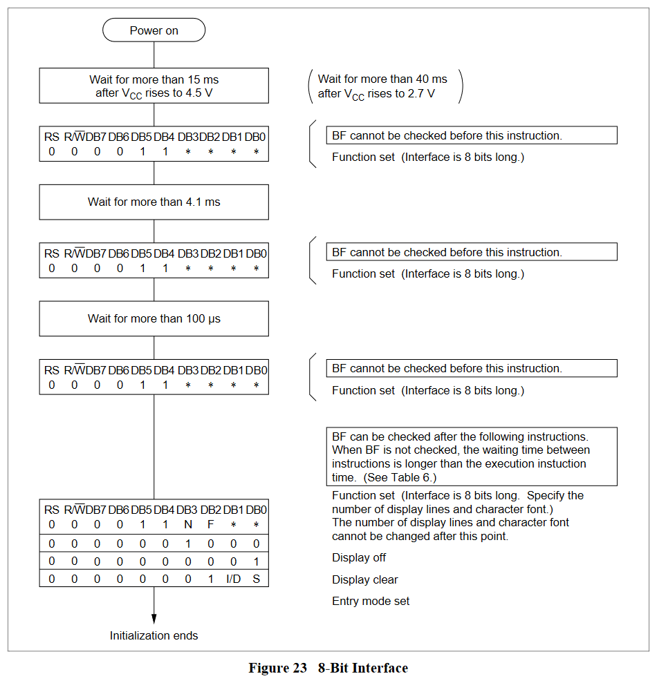
Now, let’s take a look at how to properly initialize the LCD:
| |
The top half is basically what we discussed here . Then comes the long list of commands taken straight from the HD44780 datasheet:
Some important differences:
- Make sure to turn on the LCD
- The LCD Clear function really does require a pretty substantial delay, otherwise, it will act unpredictably and give you intermittent faults. I took the value of 2000ms from the
LiquidCrystalArduino library, and it seems to be working fine on my generic Chinese surplus LCD.
Otherwise, its pretty much a direct copy from the datasheet.
Then, I implemented the core functionality, which ultimately didn’t get used in the interrupt-driven version, but still a useful tool to debug stuff anyways.
| |
I’d like to bring your attention to the LCDWriteChar() function. Notice that it is exactly the same as LCDData(), just sans the toggling of RS.
Alright, that’s it for part 1A, you should now have a pretty good idea of how to implement basic I2C functionality in the STM32 microcontroller family, and also how to use the MCP23017 I2C I/O Expander and any HD44780 based 16×2 character LCD.
In part 1B, I’ll show you how I implemented an LCD driver that is non blocking, i.e. you don’t have to wait for the LCD to finish updating before program flow continues, the data is continuously fed using I2C event interrupts.