Yes, I was a lot more naive than I thought when I first dove into this project.
Unsurprisingly, there is a lot that could go wrong with a boost converter if you try to implement one from scratch. In this article, I’m going to discuss a few of the main gotchas that really shattered my initial expectations.
Inductor Saturation
After the success of the kinda terrible boost converter back in chapter 3, I thought it’d be cool to aim higher and actually try to design something in a more proper fashion, i.e. by setting design goals from the outset, and using formulae from appnotes to try to calculate the required component values and such.
Here are the basic parameters that I set for myself:
| Parameter | Design Goal |
|---|---|
| Nominal Input Voltage | 5V |
| Nominal Output Voltage | 15V |
| Maximum Output Current | 500mA |
| Switching Frequency | 10kHz |
| Output Ripple Voltage at Max Load | 100mVpp |
Turns out, 10kHz is woefully slow for a boost converter (or for any switchmode power supply for that matter). But lets pretend we don’t yet know that, because I didn’t, and just kept on going.
Using a formula I found in this appnote by TI , I calculated the required value of the main inductor to be 740μH. I naively did the thing that everyone does with resistors: pick the closest E12 value of 680μH. That is mistake number 1, because for such a crude circuit as the one I’m building, it really does pay to get the inductor ripple current as low as possible, and that is achieved by picking the next value up and not down, but more on that later.
Inductor Ripple Current, Rated DC Current, and Saturation Current
Ripple Current
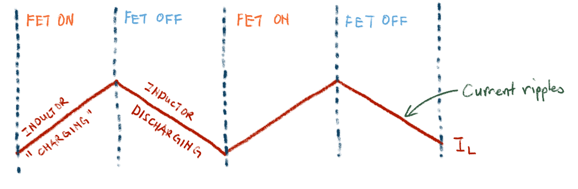
The way a boost converter works is by storing energy in the inductor when the FET is on, and releasing that energy in the form of a burst of higher voltage (hence the boost in boost converter) when the FET turns off.
There is fundamental formula for the operation of inductors that goes like this:
$$V = -L \frac{dI}{dt}$$
Don’t be afraid if you are not familiar with calculus, what the $\frac{dI}{dt}$ bit means is basically the rate of change of current flowing through the inductor. Therefore, the main takeaway from this equation is that the rate of change of current in the inductor is inversely proportional to its inductance.
When the FET turns on, the current flowing through the inductor doesn’t immediately shoot up like it would in a resistor. Instead, it steadily climbs and climbs, establishing a magnetic field around itself and in its core in the process. Or another way to look at it: it magnetises its core.
Then, when the FET turns off, the opposite happens: the magnetic field collapses, and in doing so it causes current to continue to flow through the inductor at a decreasing amperage, but in the same direction as before.
Why the same direction? Because the rate of change of current is not infinite, as the inductance is not zero. Current was already flowing through the inductor, and for it to drop to zero, it must, for a split second, continue to flow in the same direction.
So as the FET switches on and off, you could imagine that the current in the inductor increases and decreases with each on-off cycle. Thus, the idea of ripple current is born.
You may notice that there is a negative sign in the formula above. That is Lenz’s Law at play. I like to think of it this way. When you apply a voltage across the inductor in a particular direction, current flows from the more positive end to the more negative end.
Then when the voltage is suddenly taken away, current in the inductor must keep flowing in the same direction as before. The inductor suddenly becomes kinda like a battery (more accurately, it sets up an electromotive force). And for currrent to continue to flow in the same direction (through whatever else is connected to the inductor), by definition, the voltage across the inductor must reverse.
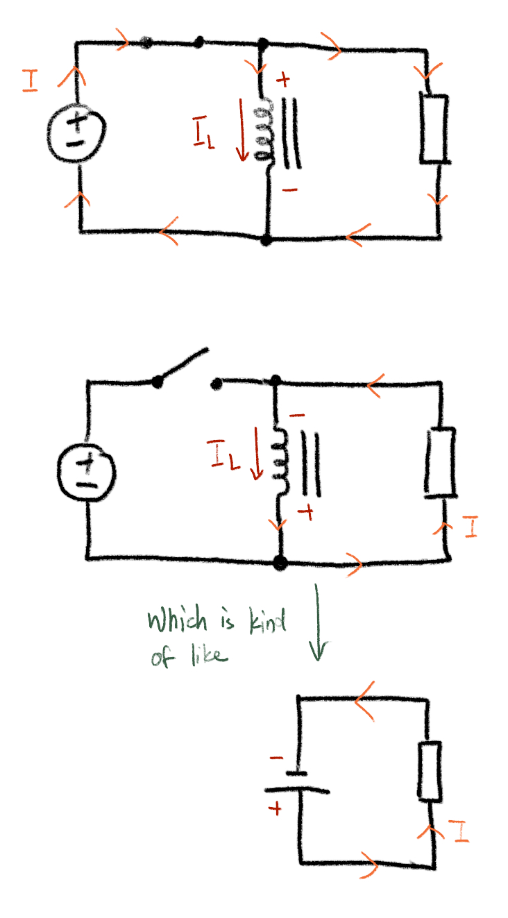
If there isn’t something present that can conduct that amount of current, the voltage across the inductor rises and rises until there is, or until there is no more stored energy left. This can be tens, hundreds, or thousands of volts.
Wired up in the right way, this rise in voltage can be harnessed to boost voltage, as in the boost converter.
Rated DC Current
This one was a big, big source of confusion for me, because different datasheets from different manufacturers seem to have different ideas for what this parameter means.
To avoid confusion, I’m going to stick with the definition that says the rated DC current of the inductor is basically the current that the wire in the inductor is rated to carry.
But, that is far from the end of the story for inductors in switchmode power supplies. If you just did some back of the envelope calculations for the current flowing through the inductor, and selected one with even a generous current rating, you will be in for a surprise. Enter, saturation current.
Saturation Current
Disclaimer: this is going to be a really hand wavy explaination of what inductor saturation is
First, we need to note that many of the inductors used in switchmode power supplies are wound around some sort of ferrite core (or more accurately, some flavour of ferromagnetic material). You could think of the core as being made up of a whole bunch of tiny magnets, known as magnetic domains.
Ordinarily, those magnetic domains are strewn about in random directions in the core, their “magnetisms” cancelling each other out. So, overall the core is just a hunk of iron based material, with no magnetism at all.
Like we were discussing above, when the FET is on, current flows through the windings of the inductor, and thus set up a magnetic field. This causes the individual magnetic domains in the core to align, the core is thus magnetised. If the FET weren’t switching, and a steady current were flowing through the inductor, the inductor will become a magnet and attract the usual stuff that can be attracted by the magnet. Those aligned magnetic domains are the inductor’s way of storing energy.
But as you can imagine, there are only so many magnetic domains available in a given piece of material. At large enough currents (and thus large enough magnetic fields), all of the magnetic domains are aligned, and the core has reached its maximum magnet-ness. It can store no more energy. The inductor is thus saturated. The current when this happens is aptly named saturation current.
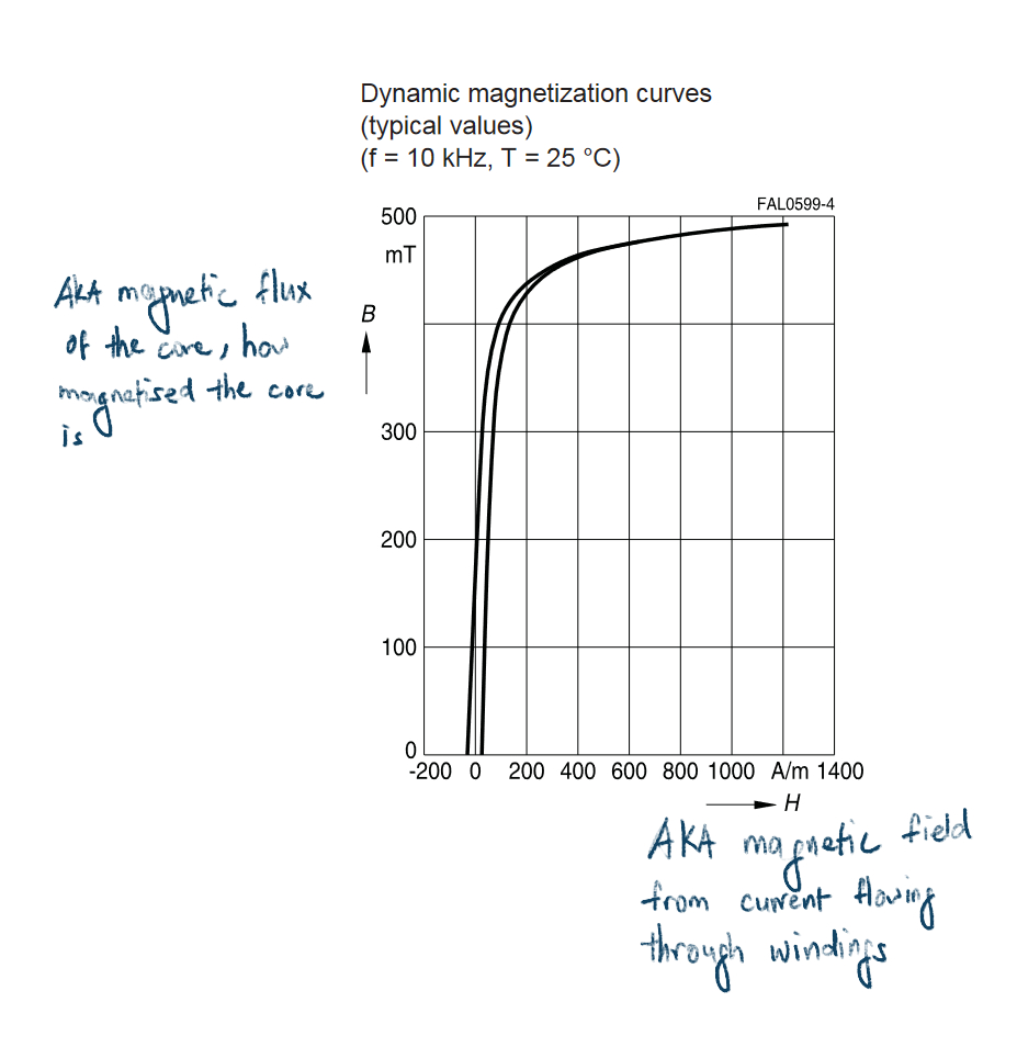
Taken from an EPCOS Datasheet
This is bad news for a boost conductor, since its entire premise is to store energy in the inductor when the FET is on, and release it when the FET turns off. If the inductor saturates before being able to store enough energy, then the boost converter can’t boost no more.
In the context of messing around with my boost converter, I simply hooked up the input to the PWM modulator to a potentiometer, which allowed me to control the duty cycle manually and eliminate any potential issues of the error amp failing to make the right corrections. No matter what duty cycle I used the output never rose above 6V.
When the inductor saturates, its inductance drops precipituously, and it acts more like a resistor. This causes the current flowing through the inductor’s windings to shoot up, since its essentially straight up wire with a low resistance. This can quickly lead to the destruction of the inductor or the FET, and you’ll have a bad day.
And also, because the error amp in the boost converter is configured to increase the duty cycle when the output voltage is too low, if the inductor saturates, the duty cycle will pretty much be maxed out. This means that for the majority of the time, the FET is basically shorted across the supply rails, and well, lets just say it got so hot that I could smell it.
Solving the problem
Larger inductor
One of the most straightforward ways of solving this whole saturation current problem is to use a larger inductance value. Basically what this does is it reduces the amplitude of the ripple current across the inductor. Therefore, if the inductor is sized such that the average inductor current, given by the formula:
$$I_{L} = \frac{V_{OUT} \times I_{OUT(MAX)}}{V_{IN}\times \eta}$$
doesn’t go too near to the inductor’s saturation current, then the chances that the inductor will saturate will be lower.
Of course, things are rarely that simple in real life. Increasing the inductance brings with it a whole bunch of gotchas, including:
- The inductor is going to be physically larger
- Therefore, it is going to be more expensive
- There will be more losses, especially at higher frequencies
- There is still no guarantee that it won’t saturate
Instead, for my case anyways, there is a much much more straightforward (and obvious) way to get a step closer to solving this problem: using a higher switching frequency.
Higher switching frequency
Going into this project, I was under the impression that high frequency = complicated and bad for people who don’t know what they’re doing like myself; so I randomly decided to use a nice and leisurely switching frequency of 10kHz, thinking that it will simplify the design quite a bit and also allow me to use the rather slow MCP6004 opamps for everthing.
Turns out, 10kHz is a woefully low frequency for a boost converter. I basically set myself up for failure.
A simple way to see why at low frequencies inductor saturation can be a real issue is by considering the amount of energy the inductor has to store and deliver each cycle. The lower the frequency, the greater the amount of energy the inductor has to supply each time the FET turns off. Hence inductor saturation becomes a real issue.
Naturally, upon learning all this, I set out to increase the frequency of the oscillator to see if it fixes things. However, turns out that even doing that comes with its own set of problems. The most pressing of which is: slew rate.
Slew rate – and why using opamps as comparators is a really bad idea for oscillators
Throughout this series I have been complaining of how slow of an opamp the MCP6004 is, with its 0.6V/μs slew rate.
In an effort to reduce the slew rate required, I switched the sawtooth wave oscillator out for a triangle wave oscillator, something along these lines:
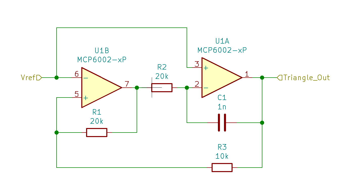
With some fiddling around, I did get it to produce a not-so-triangle triangle wave… at 12kHz.
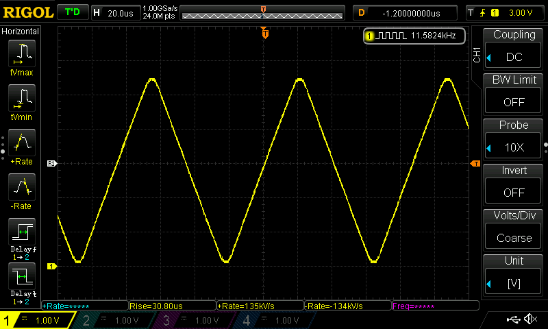
The rounded tops and bottoms are due to the opamp comparator not being able to react fast enough, as shown in this scope measurement of the output of the comparator section:
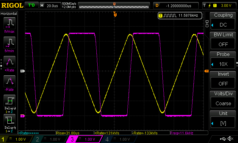
The rounded tops and bottoms are due to the opamp comparator not being able to react fast enough, as shown in this scope measurement of the output of the comparator section:
Not wanting to concede defeat, I brought out the MCP6477 opamps, which just arrived in the mail then. The MCP6477 is quite a lot faster than the MCP6004 in terms of slew rate: 8V/μs vs 0.6V/μs.
Question is: is it fast enough? No, no it isn’t.
Let’s do some quick math, for a 200kHz triangle wave with say a generous 5V peak to peak amplitude, we have a period of 5μs, and thus the ascending and descending ramps have a $\frac{dV}{dt}$ of 2V/μs. Just solely considering this, the MCP6477 should have absolutely no problems.
However, because I was trying to use the MCP6477 as the comparator that was responsible for setting up the voltages to get the integrator to charge or discharge te capacitor, the delay between the signal crossing the threshold of the comparator and the output swinging to either rail becomes important too.
Ideally, this change should happen as close to instantaneously as possible, such that the signal we get out of the oscillator is an actual triangle wave and not some rounded off abomination above.
Turns out, opamps are terrible at doing this. When I tried using the MCP6477 to get a 200kHz triangle wave, it gave me a 75kHz square wave instead. As a comparator, it simply couldn’t react fast enough to change the direction of the integrator. This is due to the way opamps are built, with components added to slow it down (compensation) to stabilise it, particularly at unity gain.
The solution: use a proper comparator IC (such as the LM393), or in a pinch the humble 555 timer would do as well since it essentially is has 2 comparators inside it. Stay tuned for that in a future article.
However, I am anticipating a whole lot of issues with ringing and getting the decoupling right, especially because these high speed devices are going to be mounted on perfboard, and even worse I’ll have to test them on a breadboard, which has all sorts of parasitics. We’ll find out soon enough.
Also, Eliott Sound Products has a really nice page explaining this discrepancy between opamps and comparators. He does a much, much, much better job explaining (and he also knows what he’s talking about), so do read it if you want to learn more.
Bonus tip: measuring inductance without an LCR meter
I had a couple of blank toroids laying around that I salvaged from some computer motherboards a long time ago. So I thought I’d wind my own inductors for this project.
Using some online calculators, I got a ballpark estimate of the number of turns of wire I would have to wind. However, it would still be nice to be able to verify its inductance.
What I ended up doing is wiring up the inductor in a high pass RL filter configuration, and measuring how much the output from the 20kHz triangle wave oscillator above was attenuated. I also compared it to some RF chokes that came in one of those kits from China.
And boy oh boy were the calculated number of turns way off, by probably an order of magnitude, assuming of course that the RF chokes are acceptably accurate. I guess that’s what happens when you make inductors with mystery toroids.
Gallery
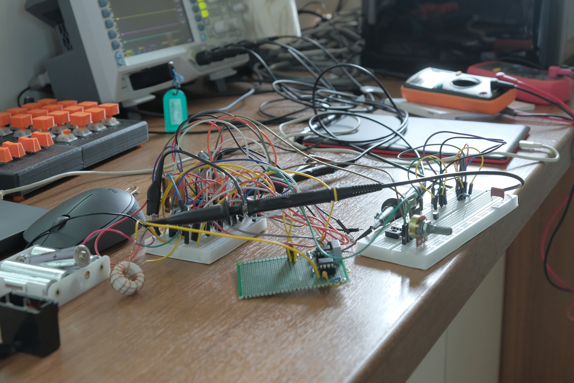
The chaos on the workbench.