This is not really a “project” in and of itself. Rather it’s a small experiment that me and my buddy Chris ran to investigate two things:
- Just how well do the figures coming out of the Patch Antenna Calculator that I botched together translate into the real world.
- How does bending the patch antenna (such as conforming it around a rocket tube) affect its parameters.
The antenna itself
This antenna was born on a chilly Friday night, in a generic teaching room in Lucy Cavendish College here in Cambridge. Our initial plan was to use Kapton tape as the dielectric, but we quickly realised that was getting us nowhere because the Kapton tape was just way, way too thin.
Then, epiphany struck, and the thought of using a milk jug as the dielectric layer just happened to surface. We grabbed one from Chris’ place, punched in the numbers from the calculator, cut up some copper foil and lo and behold, we had this:
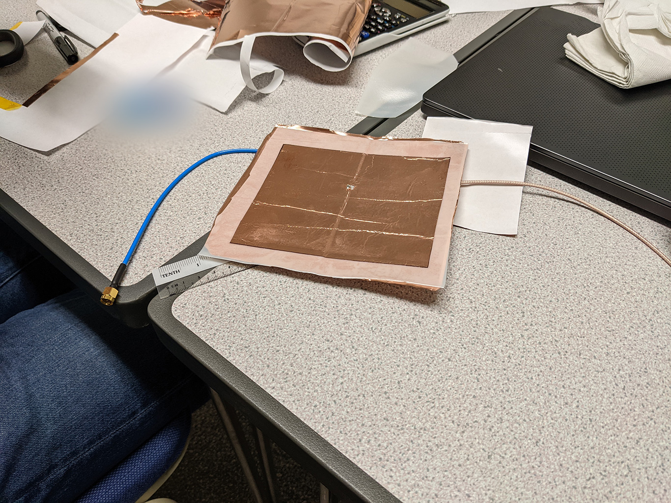
Completed patch antenna
And when we hooked it up to the NanoVNA, we really couldn’t believe that it was actually resonating near the calculated 868MHz!
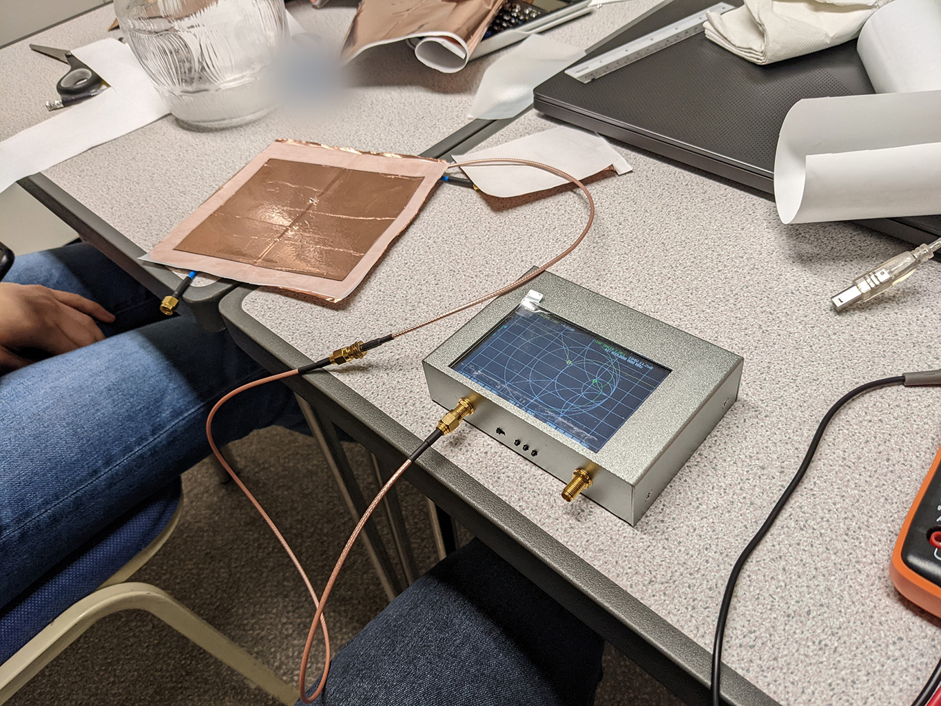
VNA measurements of the return loss
As people who knew absolutely nothing about antenna design, the fact that we were only about 30MHz off the theoretical resonance frequency - and the fact that the antenna resonated at all - really blew our minds.
One thing we didn’t expect was the milk jug kinda held its curvature when we let go of it after bending it. That made testing the behavior of the antenna when it was bent really easy.
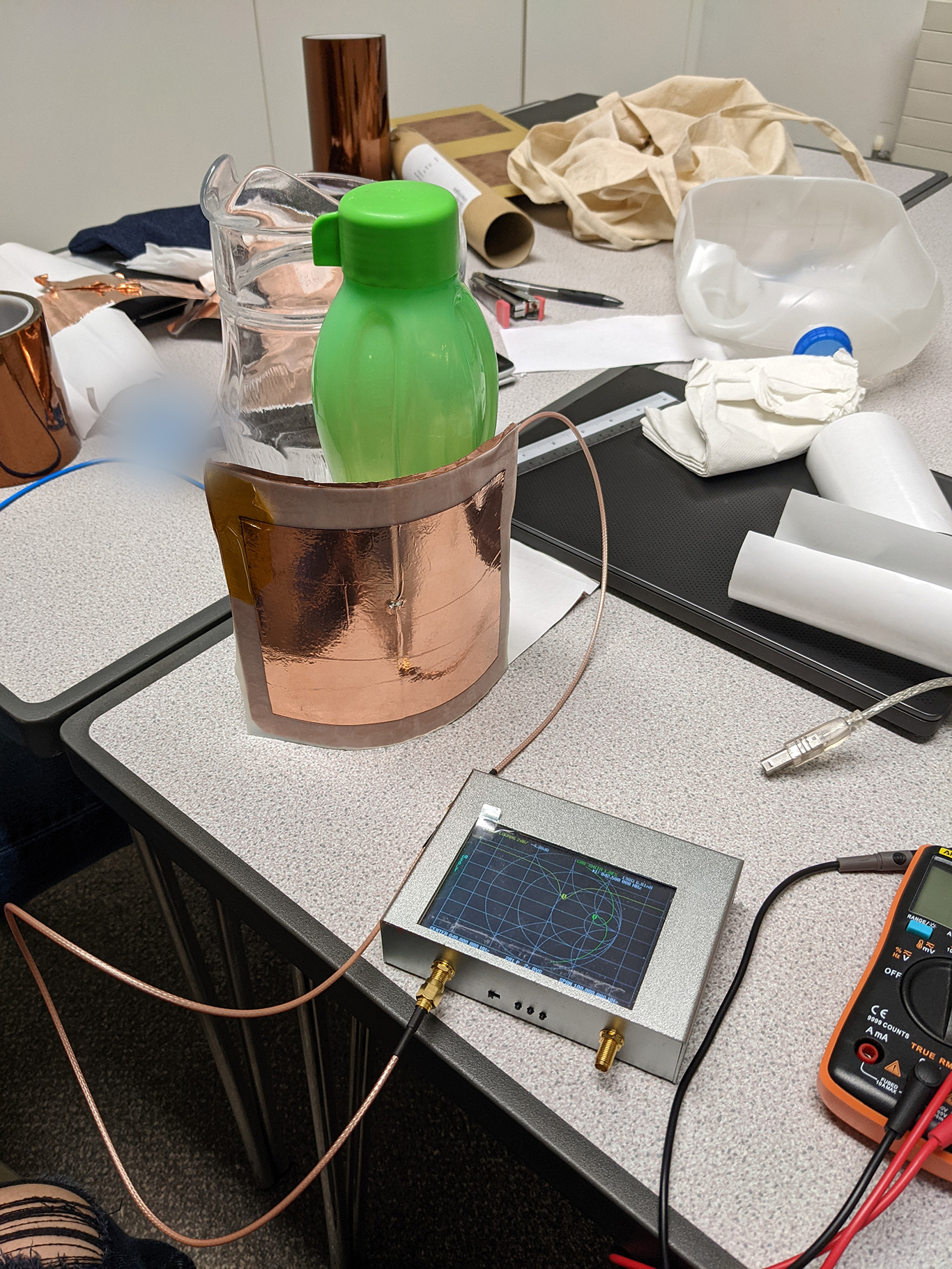
VNA measurements of the curved patch antenna, with quite a high-tech setup here
An attempt in using both ports of the NanoVNA to measure the polar pattern of the antenna
This setup confirmed that the antenna indeed had a sectorial polar pattern. Read: it radiates strongest out in front, getting weaker as we move around to the back.
“Proper” VNA Measurements
Fast forward a couple of days, and a few research papers later, we were at the Design and Project office at the Cambridge University Engineering Department. I realised that I interpreted the formula for the probe feed location wrongly, which was why our original antenna had a pathetic return loss of 4dB, and an impedance of 200Ω.
Basically, the distance given by the formula was the distance from the center of the patch, not the edge. The requisite corrections have been made to the calculator, along with some fancy-ish graphics to ensure that there will be no more confusion.
We moved the patch to the right location, and I have to say, I was really happy with how well it turned out.
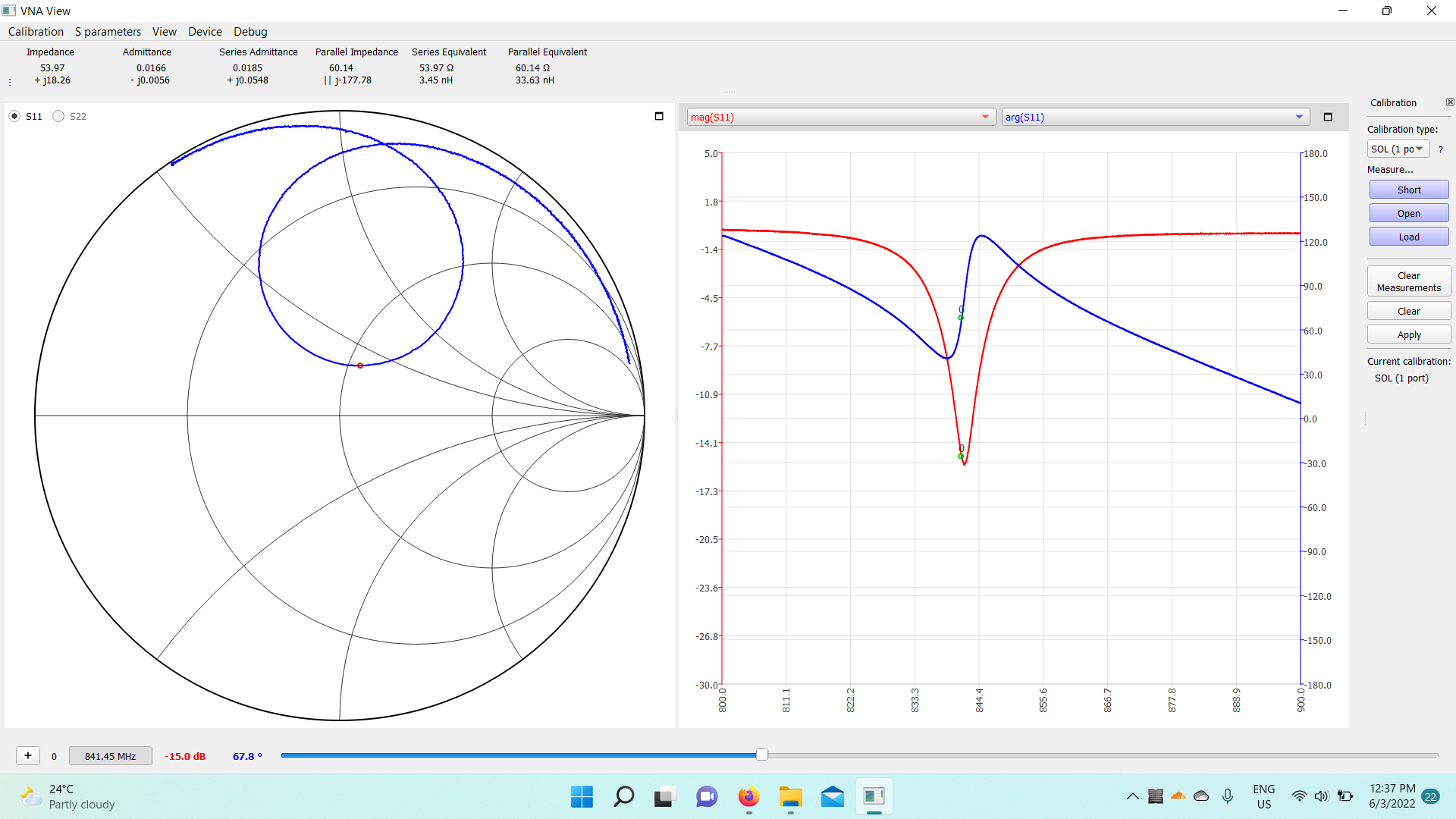
After moving the patch to the right spot, we got quite a nice response indeed, with the requisite 50Ω impedance
One thing I really want to emphasize is that this is really not the correct way to measure an antenna. All the stuff around it, be it furniture, humans, electronics or really whatever will affect the near field conditions of the antenna, altering it’s response. That being said, for a crude proof of concept, this has achieved it’s goal beautifully.
Where to next?
Now that we know the formulae work, and that curving the antenna doesn’t drastically shift its resonance frequency, coming up with designs to plug into Feko would be a lot easier and quicker.
At the moment of writing, we are currently looking into simulating 3 of these probe feed antennas used in a ring around the rocket tube to get an omnidirectional polar pattern. Once we get that done and figured out how we were going to fabricate the thing, word is that we would get to go to an actual RF anechoic chamber to do some proper analysis (!!!!).
You’d bet that I’d be documenting that here.
Until then, thanks for tagging along!
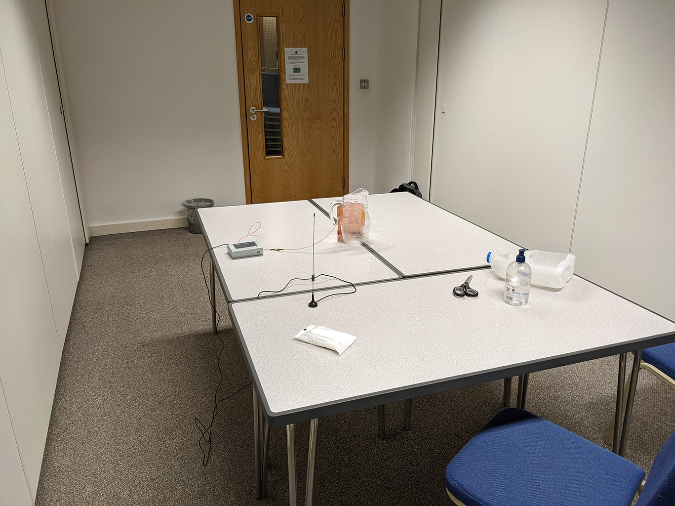
More pictures of the setup we had to work with
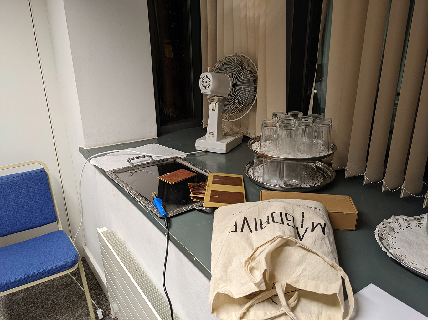
Using such a low budget setup really did bring back very fond memories of my early days doing electronics, when I had extremely minimal equipment, and everything was just pure joy!
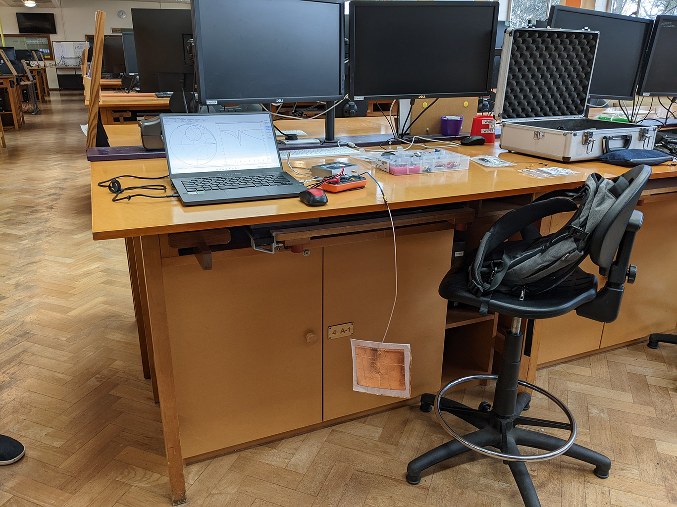
Measuring the corrected patch antenna in the DPO