So here’s the situation, I accidentally ordered the parts for the Inline Microphone Preamp Project … to Malaysia.
One month and a trip to Portugal later, I finally got the chance to use the electronics lab here in Cambridge for the first time to asesemble this thing (thanks Elena for bringing the stuff over for me!), and in good old DIY analog electronics fashion, it didn’t work first time.
Turns out, the SOT-89 footprint in KiCad has it’s pins in the opposite order from those in the NXP datasheet for the PBSS4540X and PBSS5540X transistors I was using.
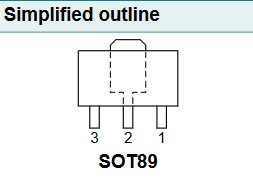
NXP Datasheet Footprint
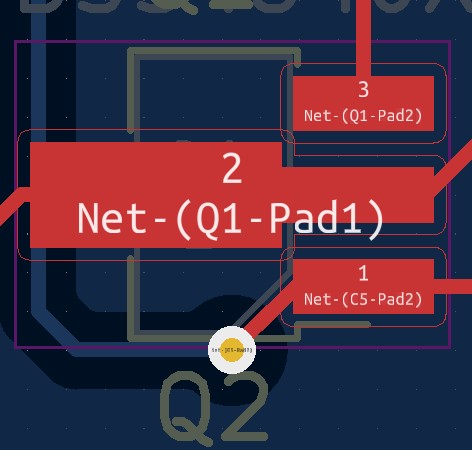
KiCad Footprint
Full disclosure here, the PBSS4540 and PBSS5540 were not in any of the included libraries in KiCad, so I did create their symbols and assigned pins manually. So it is my own mistake, I get it.
But, take a closer look here! Notice that if you orient yourself such that you are looking down onto the moulded plastic side of the transistor, and the tab is facing up, the NXP datasheet has the pins going 3, 2, 1 from left to right, while the KiCad SOT-89 footprint is the other way around.
Personally I think the NXP one is just unnecessarily unintuitive, but this just goes to show just how silly things like this can ruin your day.
I managed to overcome this issue by mounting the transistors vertically after flipping them.
Now the amplifier shows all the correct operating point voltages as indicated by the MicroCap simulation. Only thing is, it is really noisy, and is basically unity gain…
So yeah, we’re not done yet with this one…
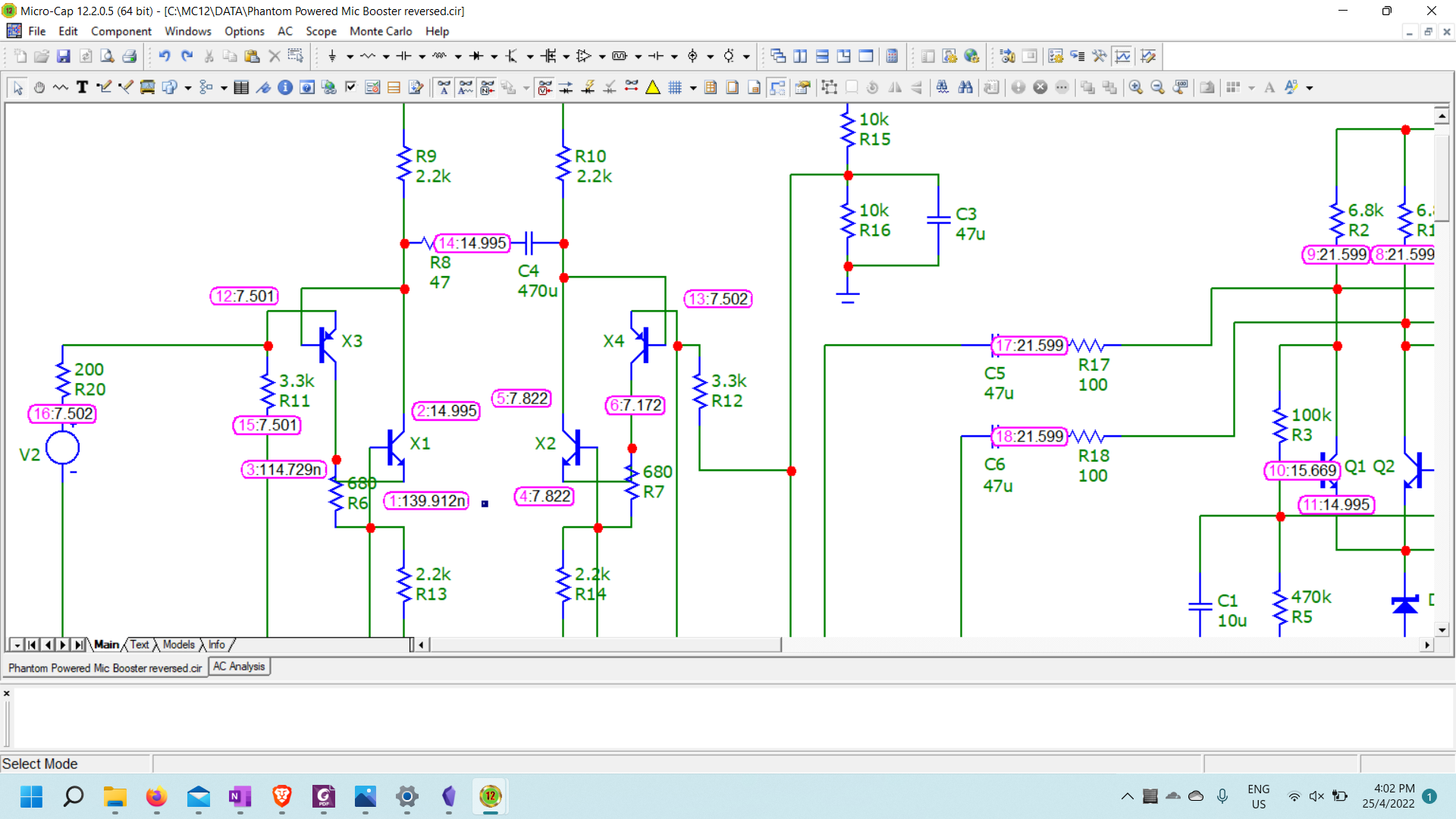
Expected node voltges of the erroneous case. I also made the mistake of swapping the two transistors of the right branch during assembly, which coincidentally caused it to have sort-of-correct operating point voltages, which caused quite a bit of a red herring chase. These voltages were almost exactly what I measured when I first powered it up.
Side Note: Don’t use black soldermask for prototypes
I used to be firmly on the camp of folks thinking that black soldermask is the best, but after assembling this board I’m not too sure.
Sure, I still think black solder mask looks really really nice, but with all these IC’s and transistors and diodes all having black plastic cases, there were multiple times throughout the assembly process where I would get confused because I thought that I missed a transistor, when it was already on the board. I just couldn’t see it at a glance because everything was black.
So yeah, I would strongly recommend that you NOT use black solder mask if you’re making boards for prototyping. It’s perfectly fine for a finished board IMO, just… not for prototyping please…