This is my attempt to try building this power amplifier from Elliott Sound Products , which was specifically designed to be a practice amplifier, in the sense that it allows electronics enthusiasts like us to practice our building and bug-tracking skills, and also to try modifying the circuit to learn some analog electronics.
I had a lot of fun building this amplifier and attempting to do some measurements on it, and I hope you will enjoy this slightly more lab-notes style post. There were some really interesting artifacts that I discovered with my measurement setup (TL,DR: trying to measure a power amp’s distortion with a Zoom H1 is probably a bad idea), that I don’t have an explanation for, and I think you’ll find them really interesting.
PS: If you’re into audio electronics, and have never checked out the ESP website, you should stop reading this article and head over there now. I have read it since I was just a little boy trying to learn a thing or two about electronics. It is truly a treasure trove of wisdom!
You probably want to have the ESP post open in another tab, because in the interest of not taking credit for work that isn’t mine, I’m not going to include the schematic here.
Construction
In his build, Elliott used stripboard, whereas I chose to use perfboard, because that was all I had on hand. One side effect of that is that I could literally place the components on the perfboard in the same layout as the schematic, since I’m not constrained to using one row per net.
That being said, in the process of trying to arrange the components to match the layout of the schematic, I overlooked some of the important component placement guidelines, such as placing the input series resistor as close to the base of the input transistor as possible to minimize capacitive coupling. It is mentioned in the ESP guide, I just wasn’t paying attention. Consequently the circuit oscillated a little, but nothing the optional zobel network couldn’t get rid of. More on that later.
I didn’t receive the BC640 PNP transistors in time for the build, so I opted to substitute those with some BC557’s. It would be interesting to see if the mismatch between the two would lead to distortion or anything of that nature.
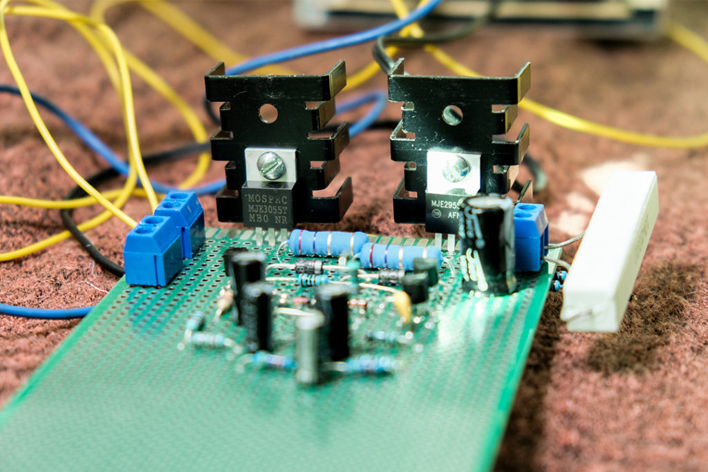
The completed amplifier build
Testing
As always is the case with these projects, stuff almost never works the first time. In the context of this exercise, that is a good thing, as it gives me the chance to try to figure out what the issue is, and hopefully learn a thing or two in the process.
Operating Point Checks
Before doing anything else, thou shall check voltages.
As recommended by this and many other ESP articles, I first fired up the amp with a series power resistor to make sure that the amp doesn’t self destruct if there is a wiring mistake. I used a 10Ω 10W resistor, since its all I had, but you should definitely use something higher.
Upon powering up, the circuit instantly drew almost 2 amps with nothing connected, and the 10Ω resistor heated up fast. Thank god I didn’t skip this precaution. After some careful cross checking with the schematic, it turns out that I had accidentally connected the base of the MJE2955 to ground, shorting it out. Oops…
After fixing it, I proceeded to check the voltages at all the nodes specified in the schematic on the ESP article, and immediately, a lot of them were off. Initially I thought its because I substituted some of the resistor values for close matches, or maybe its to do with the mismatch between the BC639 (BC63916) and the BC557; but after some thought, neither seemed to be able to explain the anomalies I was seeing.
I tried feeding in a signal… and nothing came out
Turns out, I forgot to connect the collector of Q1 and the base of Q2, meaning that nothing was driving the output stage. Since the circuit relies on feedback to set the output to mid rail, it also explains why all the voltages were off. Double oops…
| Nodes within the circuit | Voltage before fixes | Voltage after fixes |
|---|---|---|
| Output (before the DC block capacitor) | 16.67V | 12.69V |
| Across the 2.7Ω resistor | 81mV | 150mV |
| Base of Q3 | 17.89V | 13.97V |
| Base of Q4 | 15.79V | 11.40V |
| Junction of R6 and R7 | 21.5V | 19.0V |
| Junction of R1 and R11 | 21.4V | 21.4V |
| Emitter of Q1 | 11.55V | 11.3V |
| Collector of Q1 | 3.28V | 0.6V |
After these fixes, the amplifier drew about 30mA with nothing connected, and the voltages were much closer to those specified in the ESP post, which I took as signs that everything was working as intended.
Oscillation Checks
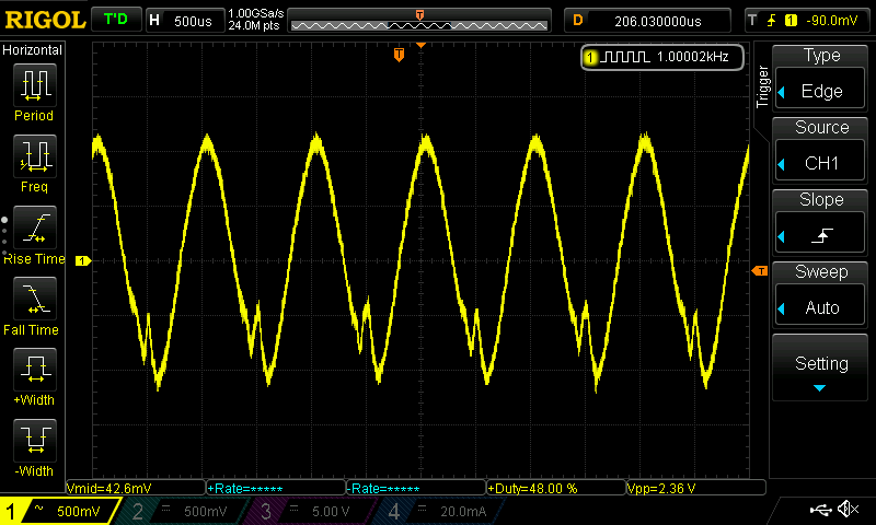
At the very beginning of testing, it was immediately apparent from how fuzzy the trace was that there was some oscillation going on, which seemed to be much more of a problem on the top half of the trace.
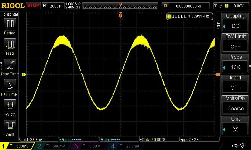
Oscillation at the upper part of the wave
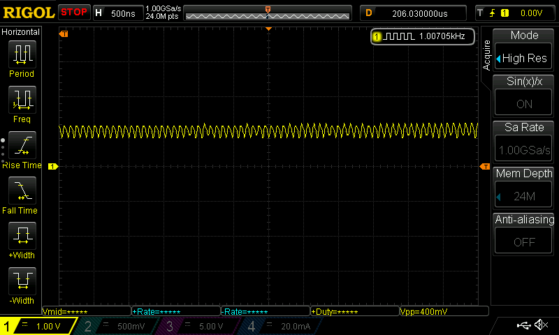
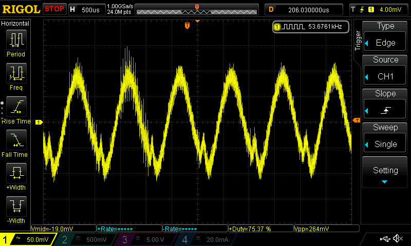
Zooming in on the oscillation
I tried probing the outputs of the input stage and the voltage amplification stage, none of them had this oscillation – it seemed to be coming from the output stage itself, which I thought was interesting (or probably not, I don’t know enough about amplifier design to say for sure).
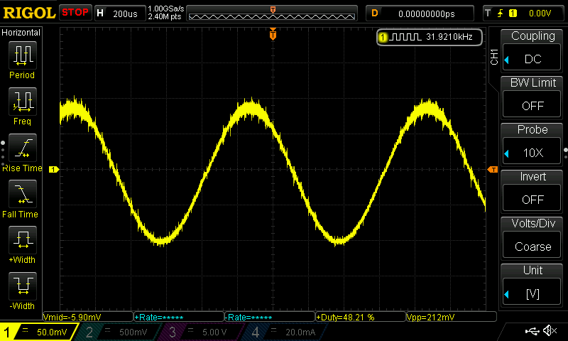
It only seemed to be present above 800mV or so.
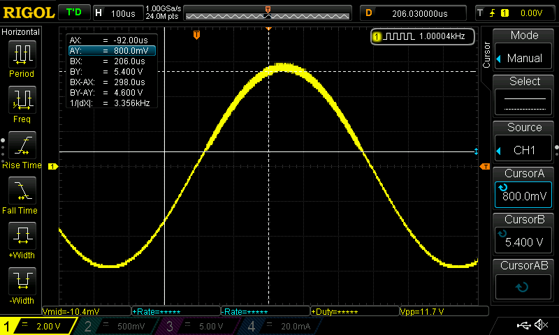
Oscillation is only present above 800mV
Adding the zobel network suggested by the ESP post immediately solved this issue, which was probably a consequence of my shoddy layout job.
Measurements
Headroom and Gain
Here’s the setup: I used Room EQ Wizard to do generate all the test tones, and analyze the output of the amplifier. The signal was generated with my laptop’s headphone output, and the amp’s output recorded with my trusty Zoom H1. I would probably have used a proper audio interface such as my Presonus AudioBox iTwo, but its in the UK, and I had no other options available. For the load, I used the same 10Ω resistor from before. Also, I added a divide by 10 resistor divider to bring the signal amplitude to something more manageable, because as it turns out, the Zoom H1 really doesn’t like large signals being fed in to it, more on that later.
First, I wanted to verify the gain of the circuit. I generated a 1kHz sine wave at a bunch of different amplitudes, and found out that the gain was indeed about 12, and the maximum output swing was about 20Vpk-pk.
From some further measurements, I found out that this circuit’s clipping behavior is rather asymmetrical, with the top half clipping quite a bit more abruptly than the bottom. I do think that its quite normal for simpler designs like this to have this sort of clipping response tho.
Clipped waveform
Frequency Response
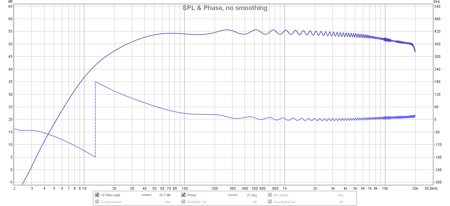
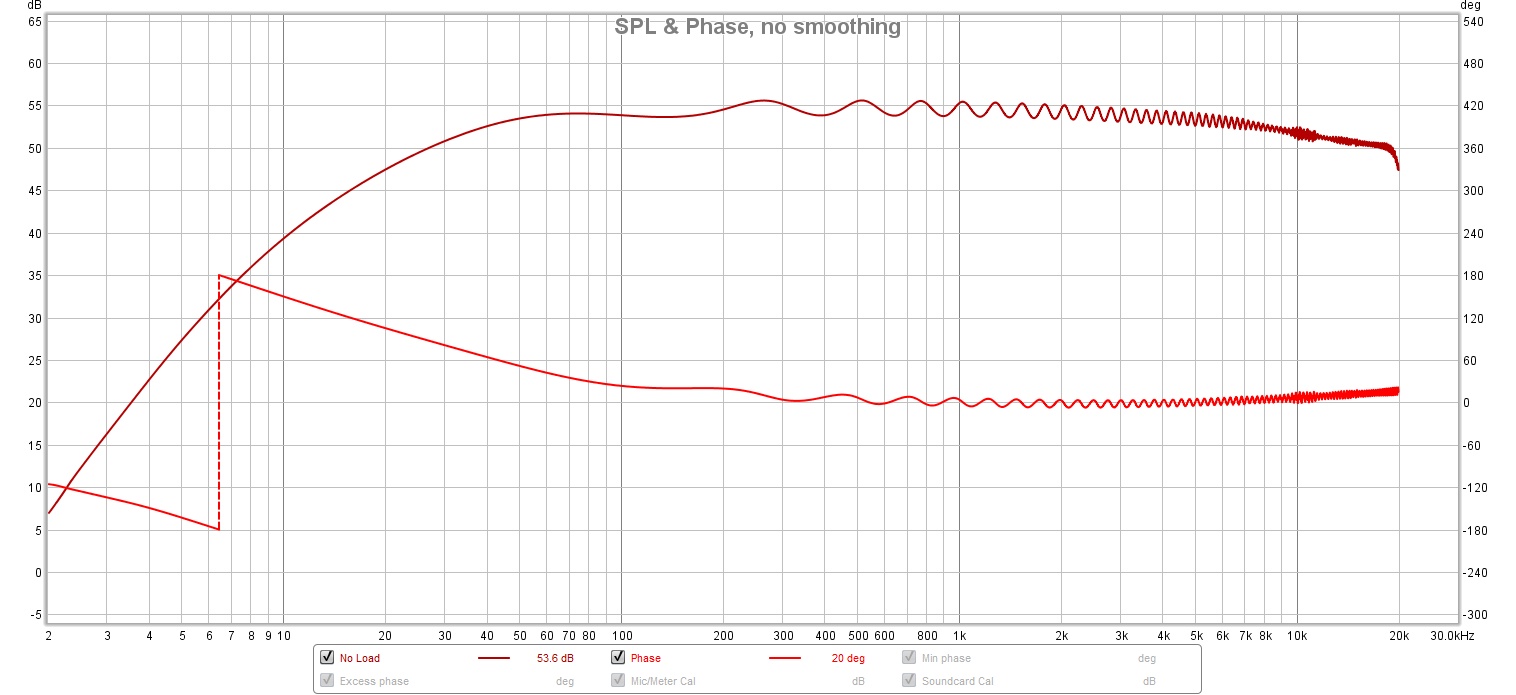
Using the setup above, I ran a Room EQ Wizard sweep to produce the following frequency response graph.
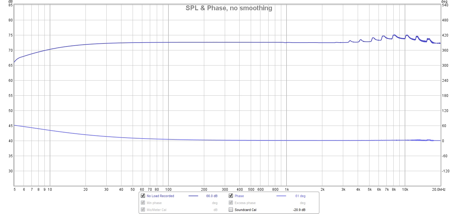
No load
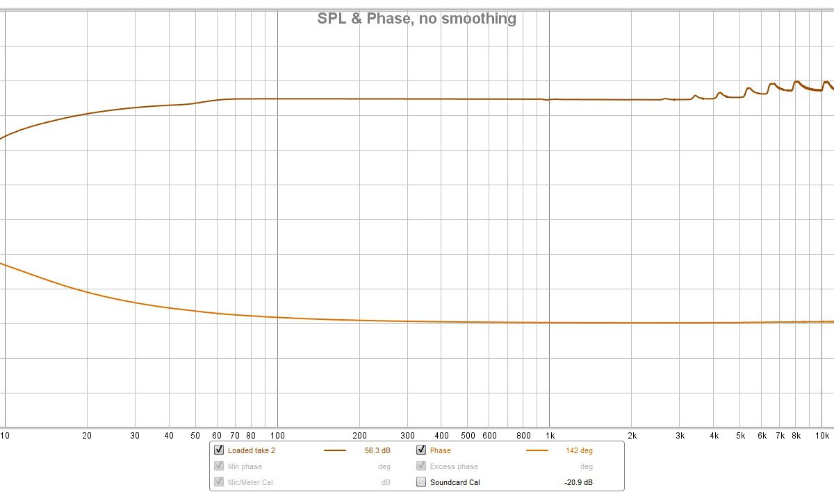
With 10Ω load
Pretty good in my opinion, everything is kind of where we expect it to be. The frequency response doesn’t change much with a load connected, except for some phase shift and more severe low frequency roll off, which is to be expected.
It should be noted that the measurement setup itself has quite a bit of low frequency rolloff, so despite having calibrated the setup, I’d take these results with a grain of salt. Here is the frequency response of a wire; ie connecting my laptop’s headphone port directly to the mic in of the Zoom H1.
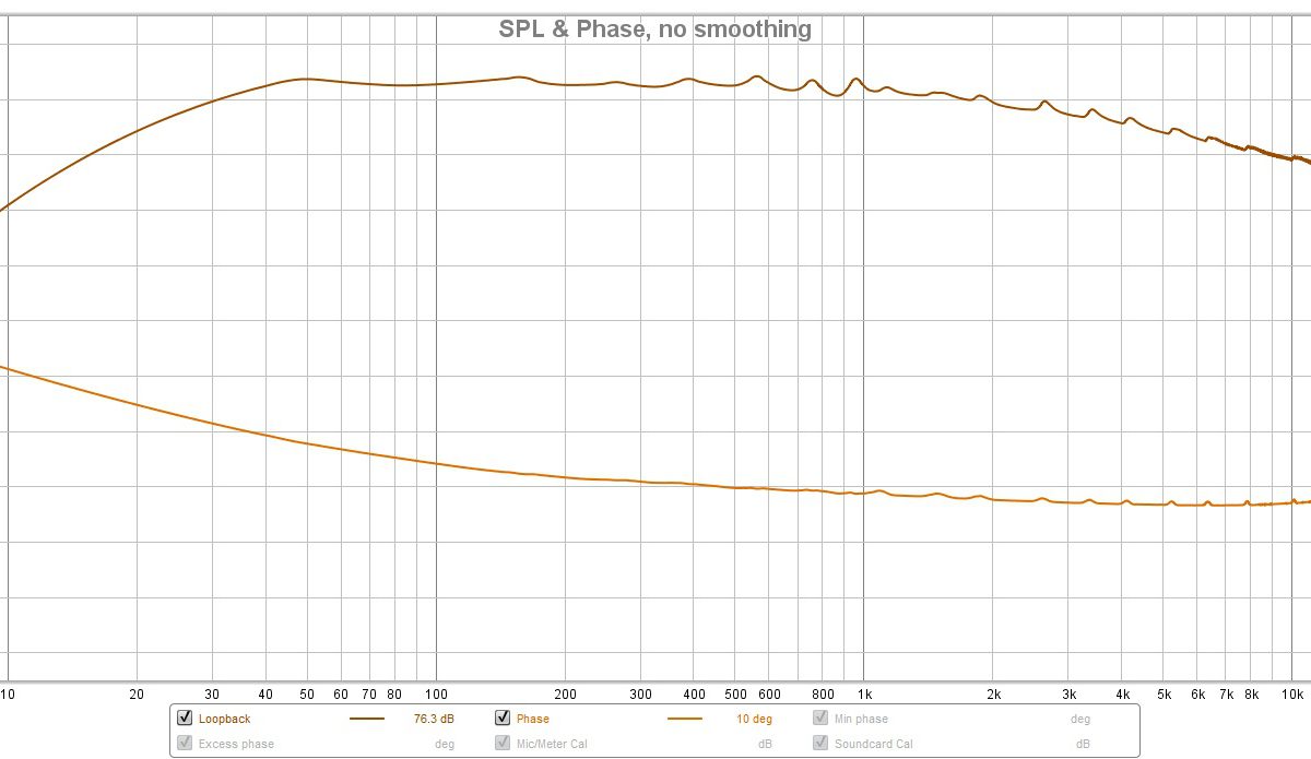
Raw loopback response
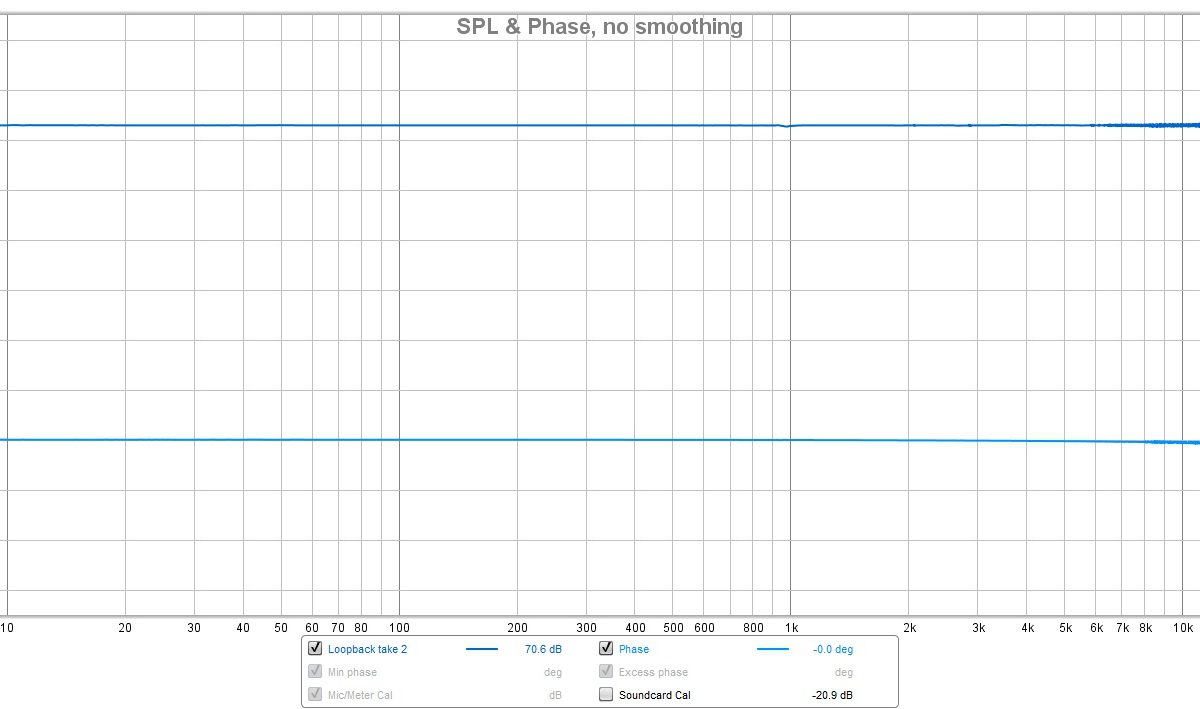
Calibrated loopback response
Distortion
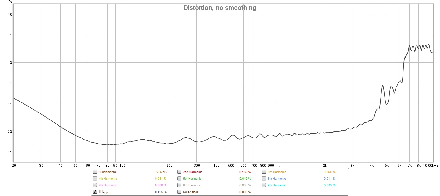
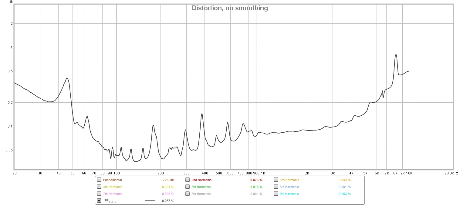
Here are the distortion plots taken from the same measurements above. These results probably aren’t that representative of the amp’s true performance, seeing that the loopback itself already has tonnes of distortion above 2.5kHz or so.
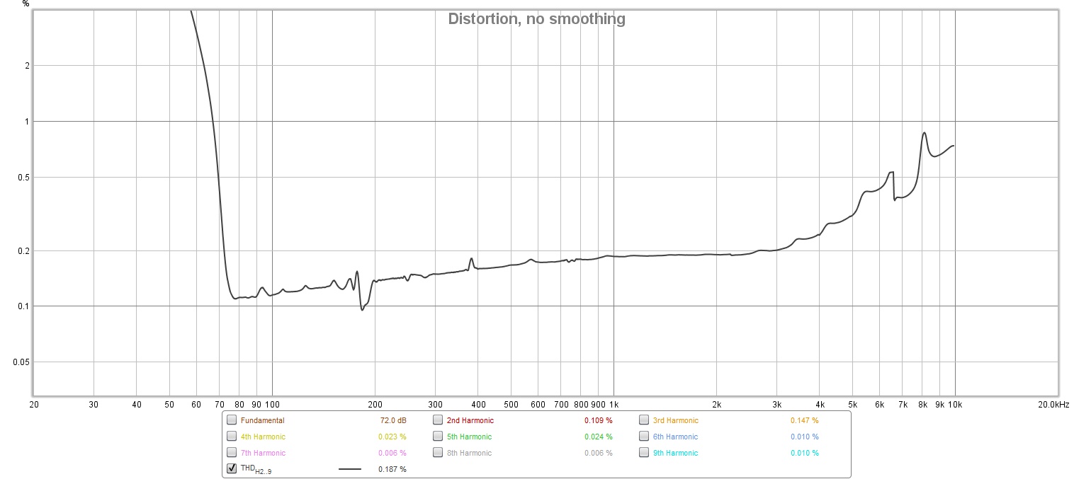
Distortion with the 10Ω load
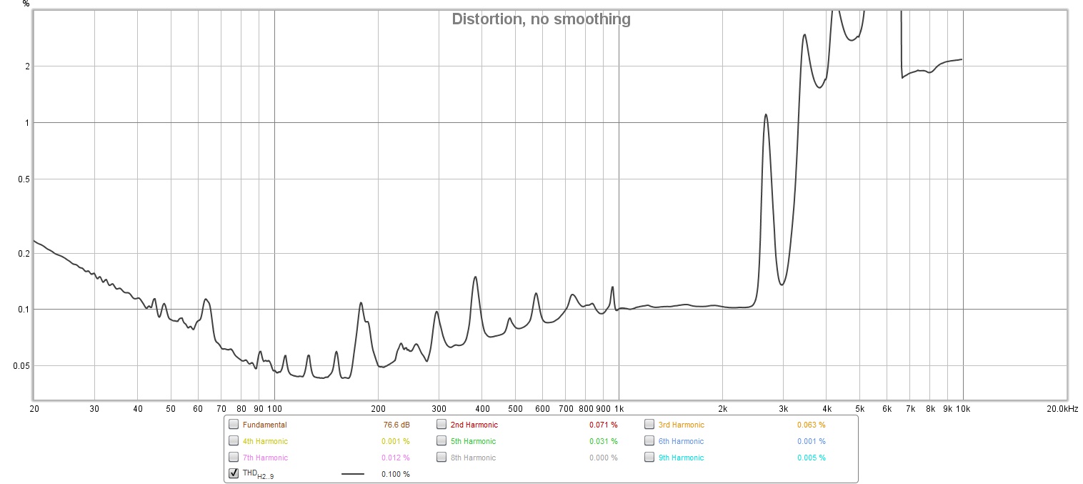
Distortion of the loopback
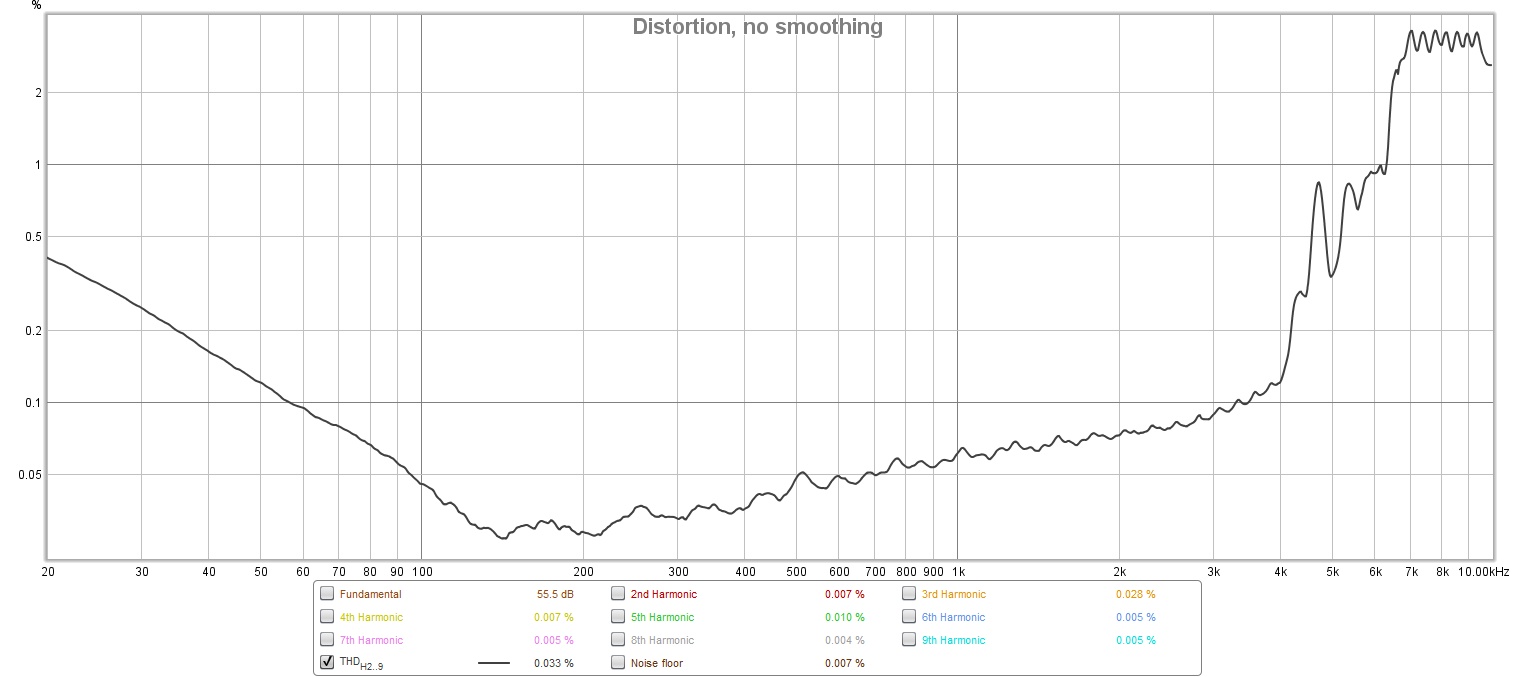
Distortion with no load
Interestingly, the HF distortion goes away when the amp is loaded, perhaps there is still some oscillation going on at higher frequencies that are dampened when the amp is loaded? I have no clue, my oscilloscope seemed to show none of that. However, the LF distortion seems to have skyrocketed for whatever reason so… I guess this measurement setup is more flawed than I initially thought.
Interesting side issue: Zoom H1’s weird behavior
Initially, I had the Zoom H1 do both the playing of the test tone and the recording of the signal. That produced some ok looking plots, but they were quite squiggly.
With 10Ω load
No load
The distortion measurements produced were also more in line with what I had originally expected, with no weird spikes or anything like that.
With 10Ω load
No load
I also did a pure (not sweep) 1kHz distortion measurement using the signal generator and RTA function of REW. It looked pretty decent too.

With 10Ω load
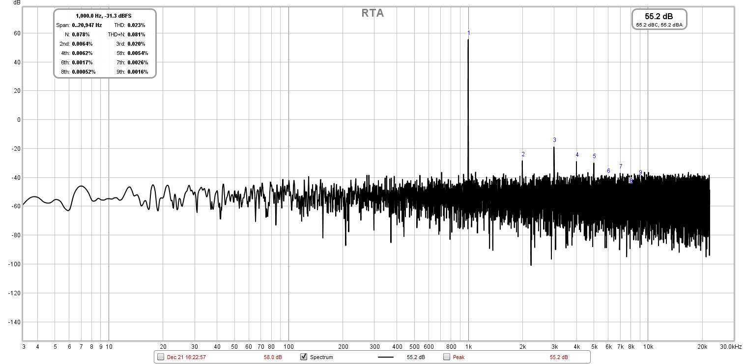
No load
However, for whatever reason I happened to be probing the output of the amp (which was connected to the mic input of the Zoom H1), and I saw this:
I thought that something had gone horribly wrong with the amp itself, but after some probing around it turns out that this nonsense was coming out of the Zoom H1’s line output port!
Also, I discovered that this issue only occurs if the signal being fed in to the Zoom H1 is relatively high in amplitude, somewhere in the neighborhood if 2Vpp. Turning down the gain dial on the Zoom H1 did little to fix it, and all the while the level meter on the Zoom H1 read around -18dB…
I think what’s happening is the large signal is causing some signal to get fed back to the supply rails of the Zoom H1’s preamp section, causing a tonne of weird self mixing, which probably also explains the squigglyness in all of the frequency response graphs.
In my mind, that made all the measurements I did before kinda dubious at best. So, I chose to go the way more elaborate route of generating the chirp into a wav file, playing it with VLC through my laptop’s soundcard, and recording the response with the Zoom H1.
A side effect of that was that it enabled me to do everything at 96kHz 24 bit (the Zoom H1 only supports 48k 16 bit over USB), which I thought was going to give better accuracy for the distortion figures for higher frequencies, and maybe it did, but I have no way of verifying any of this. Perhaps the reason for the elevated distortion figures above 2.5kHz from the graphs in the previous section is because more upper harmonics have been captured, and/or there is some really nasty aliasing going on that is throwing everything off, but this is just speculation.
I hooked the scope up to the output during one of the sweeps, and as the frequency got higher, the amplitude of the signal seemed to fluctuate a lot, even straight out of the laptop’s headphone port. You can see what seems to be the manifestation of that in HF section from the loopback frequency response graph. I did use REW’s calibrate function to try to null it out, and it seems to have worked, but I don’t think I trust the linearity of the setup at all at this point. The measurements presented here are more of an academic exercise and an excuse to have some fun, than a proper characterization of the amp’s performance.
Interesting side issue: Power supply noise and PSRR
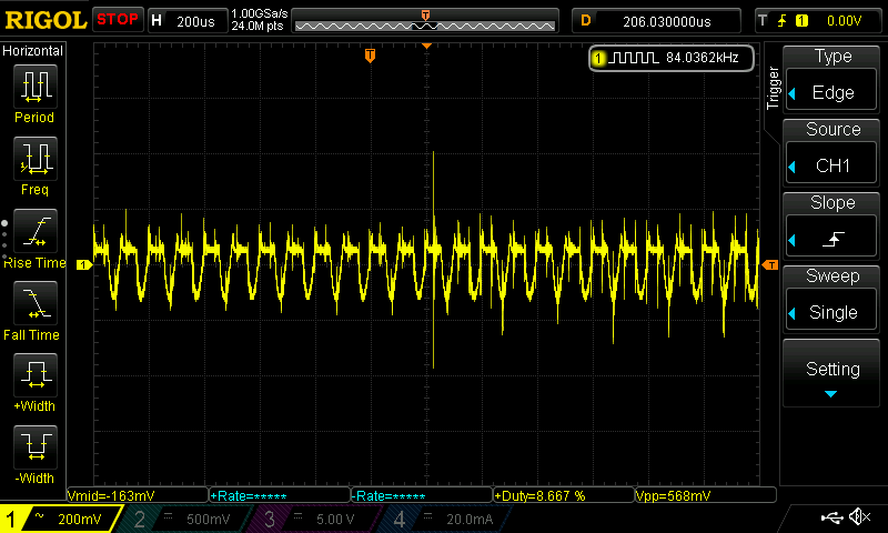
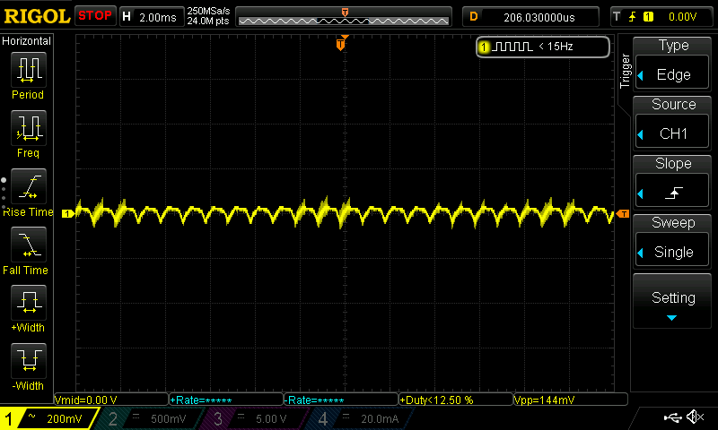
Immediately upon viewing the waveforms on the oscilloscope, I noticed just how much high frequency crap was on the signal. Being such a simple amplifier, and paying no attention to reducing loop area at all, I never expected the PSRR of this amplifier to be good anyways, but I thought I’d still include some measurements here as it might be interesting to try to fix this issue one day.
Look at all those spikes on the output of the amp, yikes!
Also, the power supply that I’m using is a cheapo Chinese switched mode power supply, and well, there is quite a lot of ripple on the supply rails.

AC coupled measurement of the supply rail
One interesting thing to realize is that where you choose to place the scope probes and how you do so really do matter for measurements like this. Take a look at these measurements, all are measuring the same thing: the supply rail in AC coupled mode. But, notice how big an effect the grounding (and thus loop area) has on the amount of HF noise picked up by the scope.
Low inductance ground lead at power terminals on perfboard
Low inductance ground leads directly across output terminals of power supply

Ground wire clip at power terminals on perfboard
There is another example of this trap for young players here .
If you want to perform similar measurements yourself, be extremely careful. Since these cheap power supplies are meant for installation in CCTV control boxes and other stuff like that, there is exposed mains wiring directly beside the output terminals. If you accidentally touch the ground lead of your scope on the line wire, well, let’s just say you won’t have fun. The hazard of electrocution is also very real. Make sure that you absolutely know what you’re doing before attempting anything like this. It is extremely dangerous.
Conclusion, and what’s next
All in all, the build itself was quite uneventful (apart from those two errors, which didn’t take that long to track down anyway). To be honest, I was kinda hoping for more to go wrong, since that would allow me to exercise my troubleshooting skills and make for a richer blog post, so when it worked, I was, ironically, kind of disappointed.
That being said, I really wasn’t expecting the Zoom H1 to exhibit the weird behavior that it did. It would definitely be interesting to do a little bit of reverse engineering to try to figure out why, although I suspect that its either ESD diodes, or some sort of power-rail referred input protection that is causing this.
There was a lot of speculation throughout the process of measuring the amp’s performance. I’d have to do more tests with different devices to be able to determine what’s the real cause of this mess.
I do have plans to try modifying this circuit to use different input and output stage topologies, such as the long tailed pair mentioned in the original ESP post to see how the behavior of the circuit changes. Now I just have to figure out how to do that in my university…
Until then, thanks for dropping by!